TM 5-3810-206-35
(2) Remove those cylinder head bolts that
(7) Repeat step (7) for the remaining 11 valves.
secure rocker arm shaft brackets to cylinder head.
(8) Install valves and operating mechanism by
(3) Remove rocker arm assembly from cylinder
reversing the procedure in steps (1) through (8) above.
head.
b. Cleaning.
Inspection, and Repair.
Clean,
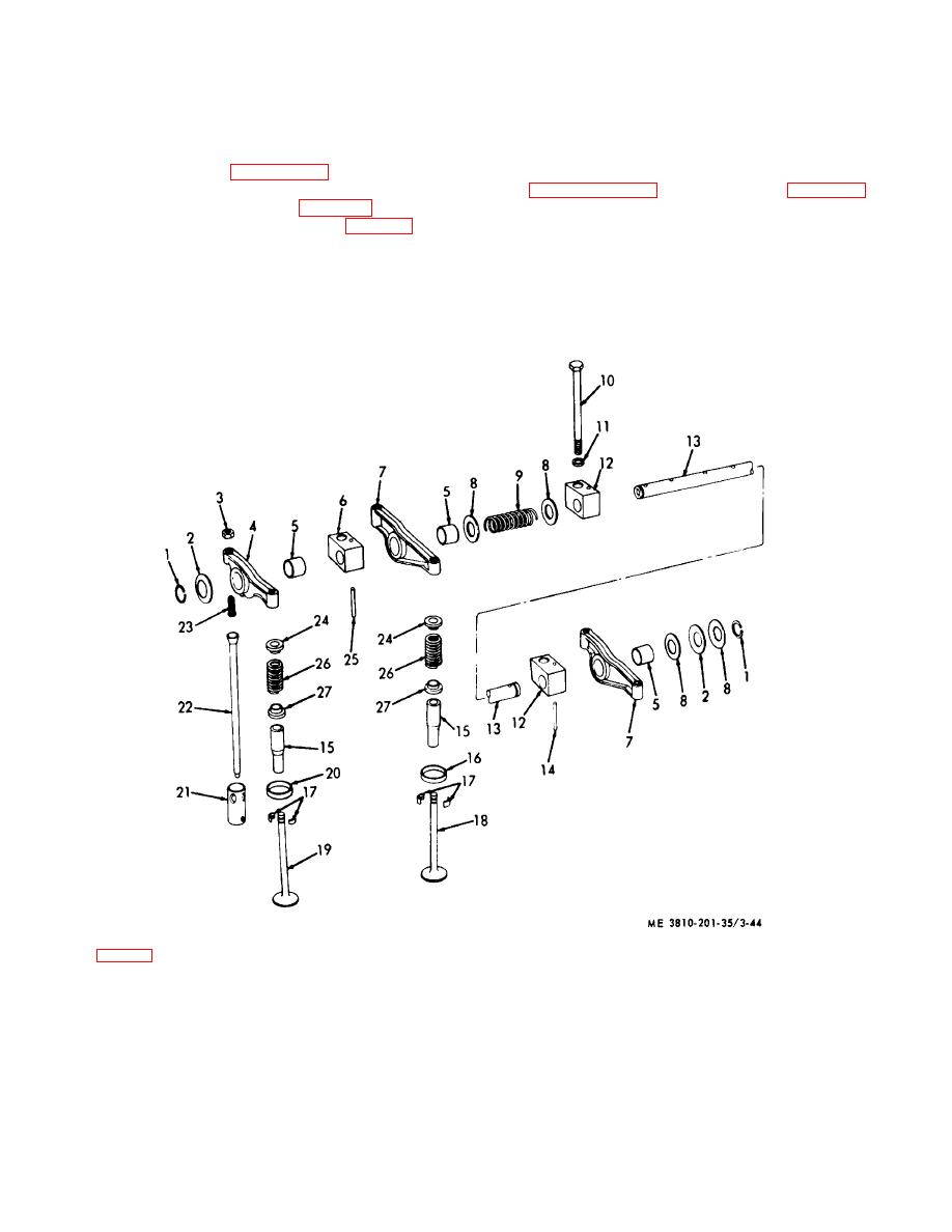
(4) Refer to figure 3-44 and remove
inspect and repair in a manner similar to that described
components (1) through (11) and (14) from shaft (13).
in paragraph 3-35b above.
See table 1-1 for
(5) Remove cylinder head (para 3-53).
dimensions, clearances, and tolerances.
(6) Compress valve spring (26, fig. 3-44) and
c. Adjusting the Rocker Arm Clearance.
After
remove lock (17) from valve stem. Release valve spring
installation of the valves and operating mechanism,
compressor and remove valve (19), seat (24), spring
adjust clearance of rocker arm (TM 5-810-206-12).
(26), spacer (27), and guide (15). Remove seat (20)
only when replacement is required.
KEY to fig. 3-44:
1
Ring
7
Rocker arm
13
Shaft
18
Valve
23
Screw
2
Washer
8
Washer
14
Pin
19
Valve
24
Seat
3
Nut
9
Spring
15
Guide
20
Seat
25
Pin
4
Rocker arm
10
Screw
16
Seat
21
Tappet
26
Spring
5
Bushing
11
Washer
17
Lock
22
Pushrod
27
Spacer
6
Bracket
12
Bracket
Figure 3-44. Valves, pushrods, rocker arms, and shaft, exploded view.
3-54


