TM 5-3810-207-20/TO 36C23-3-37-12
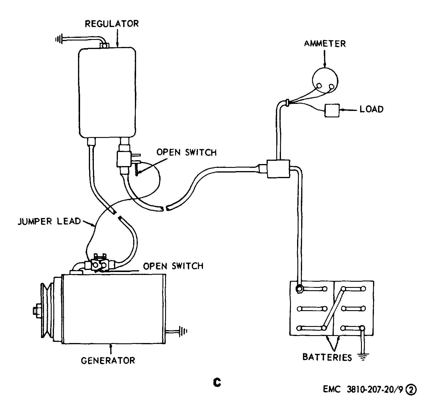
C-Electrical connections for polarizing generator
Figure 9 - Continued.
contact bracket until the specified
airgap is obtained. Secure the
adjustment by tightening the two
screws.
(g)
Push down on the voltage regulator
armature until the voltage regulator
contact point barely touches the
adjusting screw. Measure the
airgap between the coil core and the
armature of the voltage regulator.
Do not measure between the core
residual brass pin and the armature.
The correct voltage regulator airgap
is 0.084 inch.
(h)
Adjust the correct regulator airgap
to 0.115 inch in the same manner
as for the voltage regulator unit
described in g above.
(2)
Electrical adjustments. Install set of test
adapters as illustrated on figure 9.
Note.
Refer to C figure 9 and polarize the
generator.
(a)
Cutout relay closing voltage. With
voltmeter connected as shown in D,
figure 9 start the engine and slowly
increase speed until the cutout relay
contact points close. Observe
voltage
reading
at
which
this
occurs. It should be 25 to 27 volts.
If adjustment is necessary turn
cutout
relay
adjusting
screw
clockwise
to
increase
or
counterclockwise to decrease the
closing voltage. Set closing voltage
at 26 volts.
34