432. Carrier Engine Oil Pump Assembly Cleaning,
433. Carrier Engine Oil Pump Assembly Reassembly
Inspection, and Repair
and Installation
a. Cleaning. Clean all parts with an approved
a. Reassembly. Reassemble the carrier engine oil
cleaning solvent and dry thoroughly.
pump assembly in the reverse of the numerical sequence
as illustrated on figure 223.
b. Inspection and Repair. Inspect all parts for
b. Installation.
excessive wear or damage. Inspect the gears to check
for excessive backlash between teeth. There should not
(1) Install the carrier engine oil pump assembly
be more than 0.010 inch between teeth. Inspect the
as illustrated on figure 222.
clearance between the gear teeth and pump body. The
(2) Install the carrier engine oil pan (para.
clearance should be between 0.003 and 0.004 inch.
Replace or repair all defective parts.
Section XXXVII. CARRIER ENGINE CONNECTING ROD AND PISTON ASSEMBLIES
435. Carrier Engine Connecting Rod and Piston
434. General
The carrier engine pistons are made of aluminum
Assemblies Removal and Disassembly
alloy and are grooved for four piston rings. The two upper
a. Removal.
grooves are for the compression rings, the second groove
(1) Remove the carrier engine cylinder head
also holds an expansion ring. The two lower grooves are
for the oil rings, the fourth groove also holds an expansion
(2) Remove the carrier engine oil pan (para.
ring. The piston pins are held in place in the piston with
two retaining rings to prevent contact with the cylinder
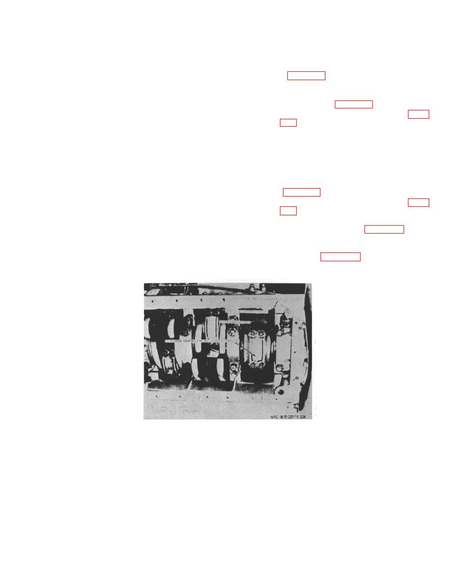
(3) Remove the connecting rod and piston
walls. The connecting rods are drilled for lubrication. The
assemblies as instruction figure 224.
connecting rods and caps are matched sets and are
b. Disassembly. Disassemble the carrier engine
marked with matched numbers. Always replace rods and
connecting rod and piston assemblies in numerical
caps as a matched set.
sequence as illustrated on figure 225.
Figure 224. Carrier engine piston and connecting rod assemblies, removal and installation
AGO 6819A
244


