(2) Clean screens and dry thoroughly.
NOTE
(3) Install screen as illustrated in figure 4-27.
The engine timing marks are stamped on
b.
Removal and Disassembly.
Remove and
the accessory drive pulley. These timing
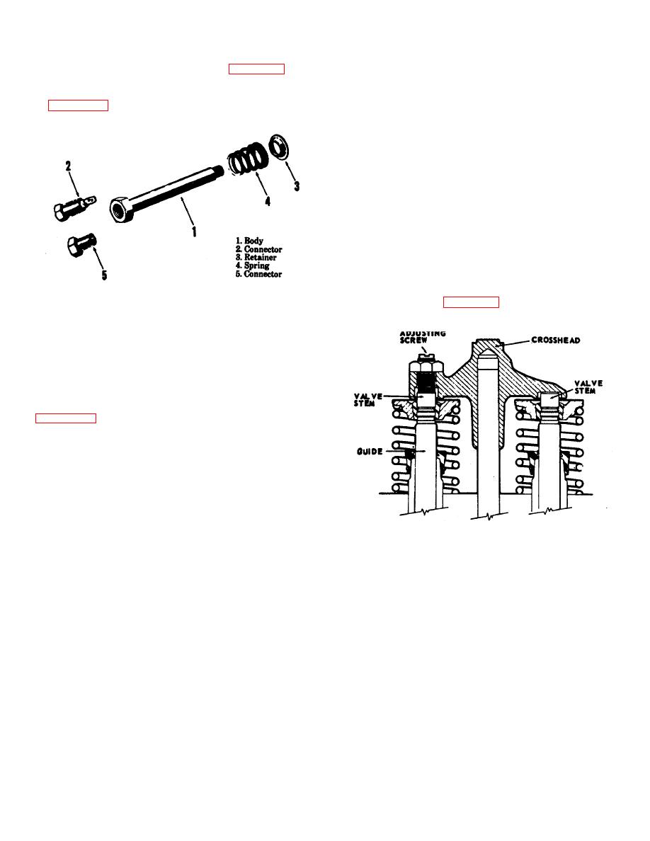
disassemble fuel inlet and drain connectors as illustrated
marks must be alined with the mark on
in figures 4-27 and 4-28.
the gear case cover whenever the
injectors and valves are adjusted.
a. Remove rocker arm cover as instructed in
paragraph 4-21.
b. Bar crane engine in direction of rotation until "1-
6/VS" mark on the accessory drive pulley is alined with
the mark on the gear case cover and the intake and
exhaust valves for No. 1 cylinder are closed.
c. Adjust the fuel injectors as follows:
(1) Loosen locknut and turn adjusting screw
clockwise until plunger contacts the injector cup, then
advance an additional 150
(2) Loosen adjusting screw one complete turn,
then tighten it to 48 inch-pounds. Tighten locknut.
d. Adjust Valve Crossheads as Follows:
(1) Loosen valve crosshead adjusting screw
Figure 4-28. Fuel inlet and drain connectors, removal
lock-nut, illustrated in figure 4-29 and back off one turn.
and installation.
c. Cleaning and Inspection.
(1) Clean all parts and dry thoroughly.
(2) Inspect for cracks, breaks, or other damage.
Replace defective parts.
d. Reassembly and Installation. Reassemble and
install fuel inlet and drain connectors as illustrated in
figures 4-27 and 4-28.
4-36. Fuel Injectors and Valve Adjustment
NOTE
For maximum engine efficiency, always
keep fuel injectors and valves in correct
adjustment. The injectors and valves
must be adjusted at the same time.
Never adjust one without the other.
ME 3810-232-12/4-29
Figure 4-29. Valve crosshead adjusting screw.
4-37


