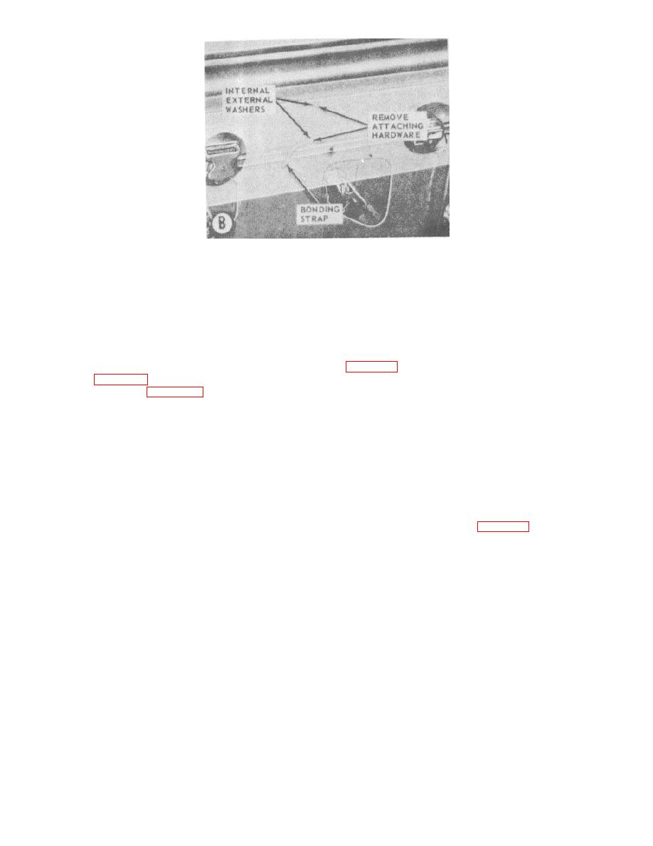
B-Bonding strap
Figure 2-1. (2) Continued
Section IV. REMOVAL AND INSTALLATION OF MAJOR COMPONENTS
(2) Install the pinion gear (6), and plate (5),
2-7. Crane Revolving Superstructure Assembly
locking clip (4), and capscrews on the bottom of the
a. Removal.
vertical swing shaft.
(1) Remove the crane boom assembly (TM 5-
(3) Install the front and rear roller assemblies
3810-232-12).
(2) Remove the front and rear roller
(4) Install the crane boom assembly (TM 5-
assemblies (para 6-32).
3810-232-12).
(3) Refer to figure 6-20 and remove capscrew
(4) Install the crane boom assembly (TM 5-
(3), looking clip (4), and plate (5) and pinion gear (6)
3810-232-12).
from bottom end of vertical swing shaft.
(4) Use a suitable lifting device and remove
the revolving superstructure from carrier assembly.
2-8. Crane Cab Assembly
During lifting, care must be taken to lift the
a. Removal.
superstructure with a straight upward motion in such a
(1) Remove the crane boom attachment as
way as not to damage the vertical swing shaft (7).
necessary (TM 5-3810-232-12).
b. Installation.
(2) Disconnect the control panel instruments
(1) Using a suitable lifting device place the
and engine controls, (TM 5-3810-232-12).
superstructure on the carrier assembly. When lowering
(3) Remove the crane cab assembly from the
the superstructure on to the carrier, care must be taken
crane base as instructed on figure 2-2.
to lower it with a straight downward motion in such a way
as not to damage the vertical swing shaft (7).
2-6


