c. Cleaning, Inspection, and Repair.
(2) Check end play of bearing to shaft for
proper clearance of 0.004 to 0.007 inch.
(1) Clean all parts with an approved cleaning
e. Installation.
solvent and dry thoroughly.
(1) Install the engine clutch assembly and the
(2) Inspect the drive plate segments for wear;
master clutch control assembly as instructed on figure 6-
inspect hub and back plate (32) and the floating plate
(31) for heat checking and distortion due to excessive
(2) Install the primary drive chain and chain
heat. Replace or repair all defective parts.
d. Reassembly.
guard (TM 5-3810-232-12).
(3) Adjust clutch (TM 5-3810-232-12).
(1) Refer to figure 6-2 and sub paragraph b.
above and reassemble the engine clutch assembly.
Section II. CRANE HYDRAULIC MASTER CYLINDER ASSEMBLIES AND
CLUTCH CYLINDER ASSEMBLIES
serving as a pressure limiter is Tee connected into the
6-3. General
master cylinder to the clutch cylinder hydraulic line.
The master cylinder piston is connected to the
operator's control lever through linkage. The piston
6-4. Crane Hydraulic Master Cylinder Assembly
forces fluid under pressure through the lines into the
a. Removal.
clutch cylinder moving the piston outward thus actuating
the clutch. When the master cylinder control lever is
(1) Drain the master cylinder.
released the clutch release springs return the displaced
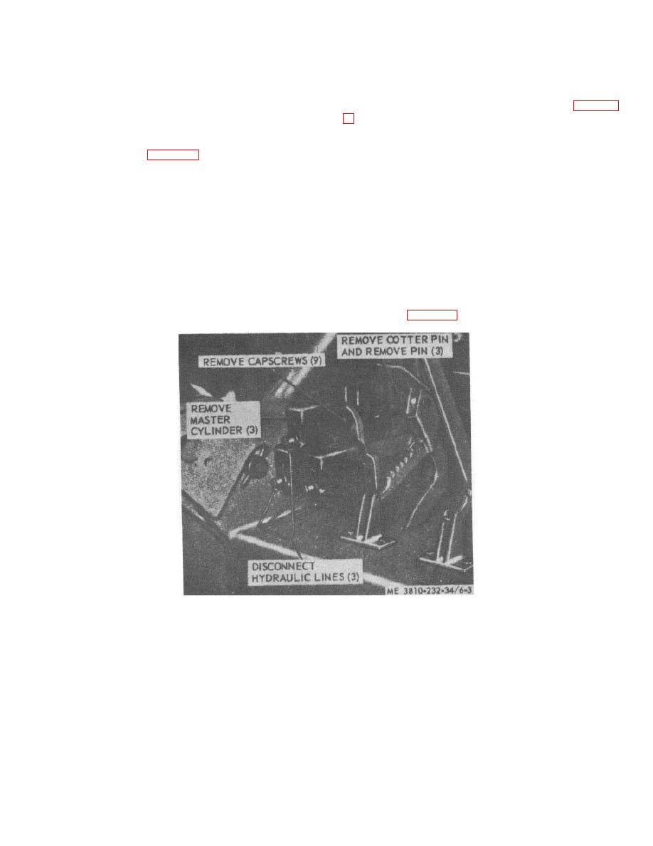
(2) Remove the master cylinder assembly as
fluid to the master cylinder. An accumulator actually
illustrated on figure 6-3.
Figure 6-3. Crane hydraulic master cylinder, removal and installation.
6-5


