TM 5-3810-289-34
cover.
(c) The idle adjusting screw is held in
position by a spring clip. Turn screw in to increase or out
to decrease the speed. Use ST-984 to adjust idle speed
while engine is running. This tool seals the spring pack
housing, permitting an accurate adjustment.
(d) Replace pipe plug when idle speed is
correct.
(e) The maximum and idle adjusting screws
are located on governor cover.
1. To adjust idle loosen rear idle adjusting
screw lock nut.
2. Screw adjusting screw in or out to get
speed required.
3.
Tighten adjusting screw lock nut
immediately after adjustment to prevent air entrapment.
(f) Some problems with excessive vibrations
have occurred at engine idle speeds.
(g) In these cases it has been found that a
substantial amount of vibration can be eliminated by an
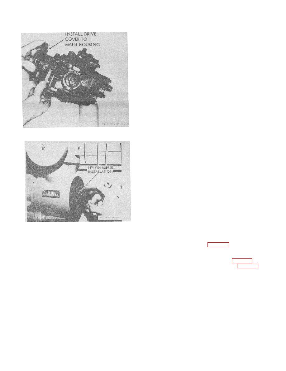
Figure 3-31. Drive cover to main housing installation.
adjustment of the engine idle speed to compensate for
component cyclic vibrations present in each particular
application.
Note. The recommended idle speed is 625 RPM
20.
(h)
This is a reference speed and is
intended as a reference point. Judicious deviation from
this speed can be made although it should be noted that
extreme care must be taken to prevent new problems by
extreme variations in idle speed.
(i)
Problems such as difficult gear
engagement can be encountered with excessively high
idle speeds. Poor load pickup can be a problem if idle
speeds are adjusted too low.
3-3. Shutdown Valve
a. General The shutdown valve controls fuel flow
from the pump to the injectors. The electric valve is
Figure 3-32. Nylon buffer installation.
equipped with a knob which will open the valve in case of
electrical power failure. Keep knob in counter-clockwise
(e)
(gages
and
position to operate electrically.
tachometers) must have high accuracy.
b. Removal Refer to figure 3-8.
Caution: Do not alter pump settings to satisfy
c. Disassembly.
gages and tachometers of unknown accuracy.
(1)
Remove screws and lockwashers
(f)
Vehicle throttle control linkage is
securing coil housing to valve housing (fig. 3-33).
adjusted so full throttle is obtained and when released
(2) Remove coil housing (1, fig. 3-34), fuel
throttle is stopped by front throttle adjusting screw
shield (8), and O-ring (4). Discard O-ring.
(throttle leakage adjusting screw).
(3) Remove spring washer (9) and plate-
Note. Vehicle throttle control linkage should have
type valve (10).
a maximum throttle stop, so when fuel pump full throttle
(4) If necessary, remove manual override
is obtained override pressure will not be on throttle shaft.
knob (3) and unscrew override shaft (7) from coil end.
(2) Governor setting.
Discard shaft O-ring (16).
(a) After fuel pump installation, engine must
d. Cleaning and Inspection.
be operated a sufficient period of time to purge all air
(1) Clean all parts except the coil assembly
from the fuel system and to bring engine up to operating
in an approved cleaning solvent.
temperature (at least 165 F. oil temperature).
Note. Do not wet the coil with solvent; instead,
Note. Idle speed adjustment should never be
wipe it clean with a lint free cloth.
made on a cold engine.
(b) Remove pipe plug from spring pack
3-13


