TM 5-3810-289-34
c. Inspection and Repair.
(1) Check drive shaft bushing for sign of
seizure or burs.
(2) Check drive shaft bushing I.D. with
inside micrometers; if worn beyond 0.7525 inch replace
bushing.
(3) Remove worn bushing using a gage
chisel or half inch pipe tap. After tapping bushing, screw
a half inch pipe cap on a close nipple and screw the half
inch nipple into the bushing. Insert a punch through the
rear of the housing and drive out the bushing.
(4) Apply a thin coat of high pressure
lubricant to a new front drive shaft bushing; press
bushing into housing flush with housing bore using an
arbor press.
(5) Line ream bushing to 0.7495/0.7505 inch
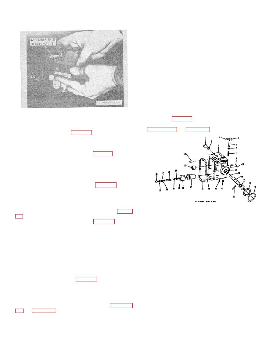
Figure 3-38. Valve assembly.
with ST-490 Ream Fixture, and a well oiled 0.750 in. (3/4
in.) reamer (fig. 3-40). Check bushing I.D.
Caution: Be sure that starting switch is in off
d.
Reassembly and Installation.
Refer to
position when checking coil.
(4) Refer to table 2-2 (5) j. for current
solenoid valve coil assembly and coil resistances.
e. Assembly.
(1) If removed, install a new O-ring on
override shaft and coat with lubricant (fig. 3-36).
(2) Screw shaft into housing until it reaches
bottom of its bore. Use depth micrometer set at 0.118
inch and check distance from face of valve housing to tip
of shaft. If necessary, screw shaft out until it is 0.118
inch below housing face. Press on knob until it contacts
valve housing; thus it will act as a stop (fig. 3-37).
(3) Seat valve into valve housing.
(4) Apply lubricant to housing O-ring and
seat in groove.
3
Housing Assembly
29
Plunger, governor
(5)
Drop spring washer on valve with
4
Clip
30
Pin, governor plunger
concave side up and piloted around valve bore (fig. 3-
5
Plug
31
Sleeve, stop
6
Nut, throttle adjusting screw
32
Spacer,
governor
(6) Place fuel shield (8, fig. 3-34) on coil
plunger
7
Nut, throttle adjusting screw
33
Drive, governor plunger
housing and secure to valve housing assembly with
8
Screw, throttle adjusting
lockwashers (12) and capscrews (11).
Tighten
9
Plate, name
capscrews to 15/20 inch-pound torque.
10 Screw, drive, nameplate
(7) Energize valve and pump fluid through
11 Sleeve, throttle shaft
valve at 300 psi. Deenergize valve; valve should with
12 Seal, O-ring
13 Shaft, throttle
stand the 300 psi load with no leakage through valve.
14 Spring, throttle shaft
(8) Should leakage exist, check the main
15 Cover, throttle shaft
body for nicks or depressions where body and place
16 Ring, snap, throttle shaft cover
come in contact. Check the rubber seal in the plate for
17 Pin, throttle stop
18 Plug, pipe
swelling or other defects.
19 Clip, governor barrel
f. Installation. Refer to figure 3-8 and install valve.
20 Dowel, ring
3-4. Fuel Pump Housing
21 Gasket
a. General. The fuel pump housing is the largest -
22 Dowel, body to cover
28 Bushing, tachometer drive gear
part of the fuel pump and contains the governor barrel
24 Sleeve
and throttle shaft. Other units attach to the housing.
25 Barrel assembly, plunger
b. Removal and Disassembly. Refer to paragraph
Figure 3-39.
3-15


