TM 5-3810-289-34
link and press link into place, figure 3-84. If sleeve type
retainer, press retainer flush to 0.010 inch below bore
surface.
Caution: Handle injector plunger with care to
prevent damage which could render it useless.
(2) PT flanged injector body.
(a) If connection threads in body were
marked for repair, clean threads with a -1/2-20 tap.
(b) Repair connection gasket surface if
mutilated with ST-542.
1. Screw pilot of ST-542 into inlet or drain
connection to be spot faced.
2. Pilot cutter of ST-542 over pilot.
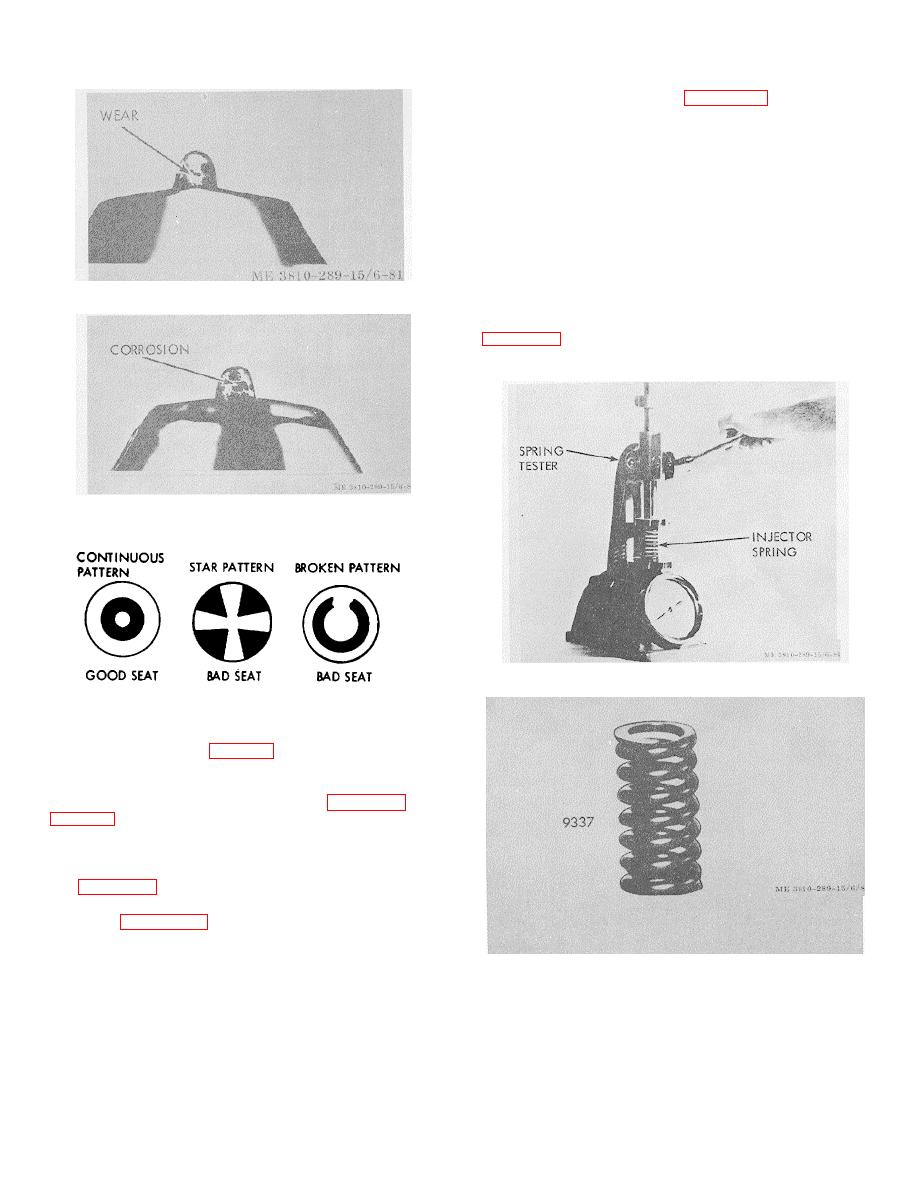
Figure 3-77. Worn injector cup tip.
e. Turn cutter until a good gasket seat is cut,
4. Clean body thoroughly after repair.
Figure 3-78. Corroded injector cup tip.
Figure 3-80. Injector spring test.
Figure 3-79. Seat pattern of plunger in cup.
of spring lengths and applied load by means standards
and dial indicator gage, table 2-2.
(c)
If injector springs compress to
dimensions shown, at less than load indicated under -
"wear limits", springs must be discarded, figure 3-81 and
f. Repair
(1) Plunger link replacement.
(a) Replace plunger link if worn excessively
see figure 3-82.
(b) A collet type hand tap holder, such as
shown in figure 3-83 may be used to pull sleeve type
injector links:
1. Place tap holder over link and tighten
holder.
Figure 3-81. Injector spring.
2. Hold plunger and give tap holder a quick pull.
Note. Do not put plunger in vise to pull link.
(c) Place new retaining ring on new plunger
3-28


