TM 5-3810-289-34
3-93; begin tightening sequence with capscrew on
opposite side of inlet and drain connections.
Caution: Excessive tightening may distort
valve seats or crack cylinder head.
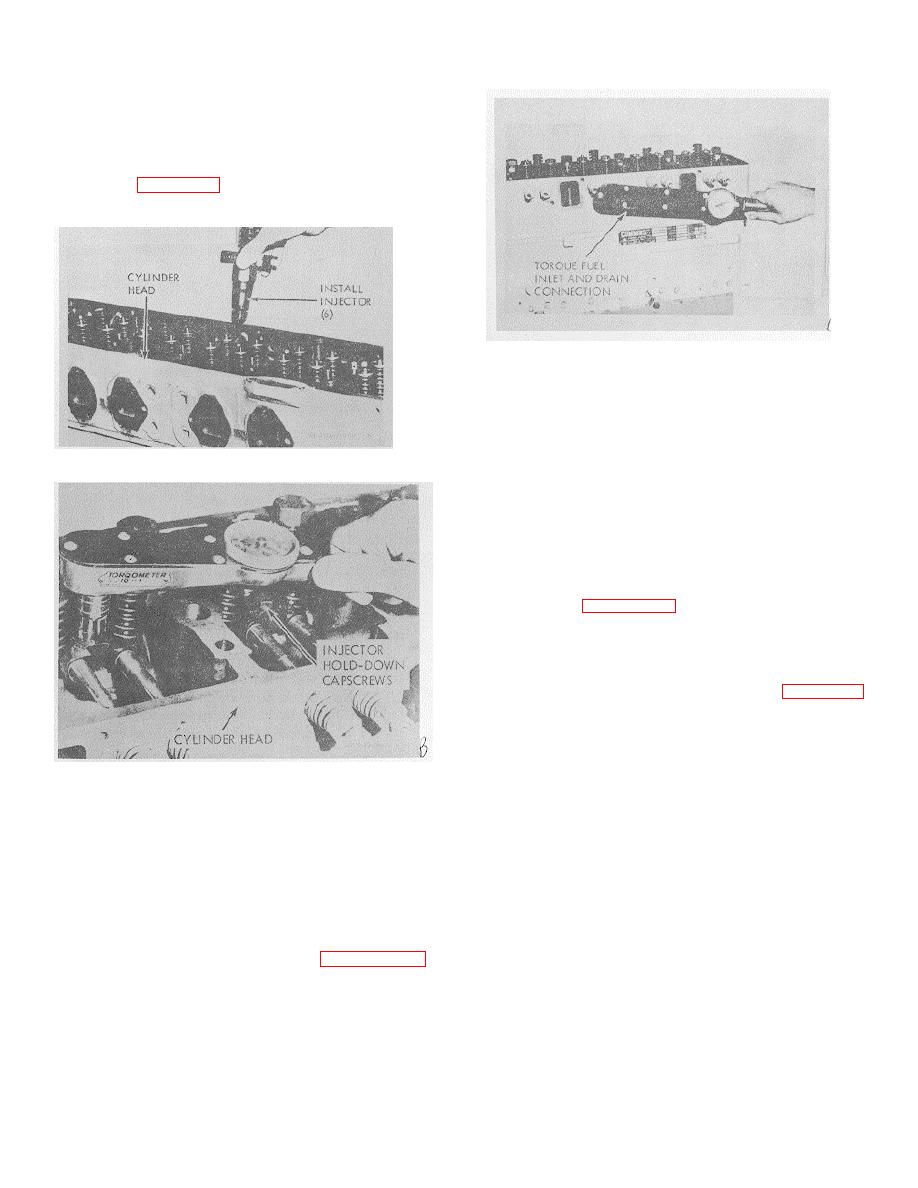
(7) Tighten inlet and drain connections to
20/25ft.-lbs., figure 3-94. Be sure that wrench engages
nuts next to connection springs.
Figure 3-94. Torquing fuel inlet and rain connection.
replacement if seat area is scratched.
(3) Lightly coat a new injector cup) on
injector body with Prussian Blue. Install in injector sleeve
and torque injector into injector sleeve evenly to
operating tension. Remove and check seat pattern. If
Figure 3-92. Installing injectors.
indicated seat width does not show at least 0.060 in wide
continuous contact, mark sleeve for replacement.
(4) Check seat depth.
(a)
Install injector assembly.
injector capscrews to 10/12 ft.-lbs. If so equipped,
torque
nylock capscrews to 12/14 ft.-lbs.
(b) Measure tip protrusion with dial indicator
as shown in figure 3-95. Injector cup tips should
protrude 0.040/0.055 in. beyond cylinder head milled
surface. Maximum allowable protrusion is 0.065 in.
c. Repair.
(1) Machine bead in sleeve seat area of
head, if not previously beaded, with ST-839, figure 3-96.
This will provide an improved seal.
(2) Install the bead cutter in ST-379-1 Seat
Cutter Holder and position with ST-843 Seat Cutter Pilot
in a drill press. Set drill press speed at not more than 75
Figure 3-93. Torquing injector holddown capscrews.
rpm. Cutter may be turned by hand using a tap wrench.
Caution: Chattering may occur if drill press
3-14. Injector Sleeves
speed is over 75 rpm.
a. Removal
(3) Place cylinder head on drill press table,
(1) Remove worn flange-mounted injector
allowing clearance for the end of the bead cutter to
sleeves by cutting them from cylinder head with a 3/8
protrude below the head surface into a pilot. The pilot
inch cutting tool) and driving out from lower end.
can be made by recessing a '%2 inch drill bushing in a
(2) Remove all foreign material from injector
plate which is centered below the drill spindle and
sleeve sealing are area.
secured in place.
b. Inspector Sleeve.
(4) Before starting drill press motor, insert
(1) Note results of water test. Leaks
cutter, adapter and pilot into injector bore to insure
indicate need for replacement. Refer to paragraph 3-30c
proper alignment.
for water test.
(5) Lift cutter, adapter and pilot, lubricate
(2) Visually check sleeves which pass the
cutter with cutting oil and start cutting operation, applying
water test for scratches on cup seat area and mark for
a steady moderate pressure.
3-31


