TM 5-3810-289-34
sanding drum powered by an electric drill. Emery cloth
may be used if bore contains ridges. Be sure to remove
nicks or burs that would damage liner packing rings as
liner is installed.
d. Inspection. Before any part is discarded or
used again a careful inspection must be performed. The
inspection should include wearing surfaces and general
over-all conditions.
(1) Inspect for corrosion on portions of block
nearest cylinder liners as evidenced by pitting. Discard
block if area cannot be cleaned, or if area is distorted.
(2) Inspect water passages for erosion
within 1/32 to 3/32 inches from liner counterbore; if not
too deep block may be resurfaced.
(3) Inspect all water passages to make sure
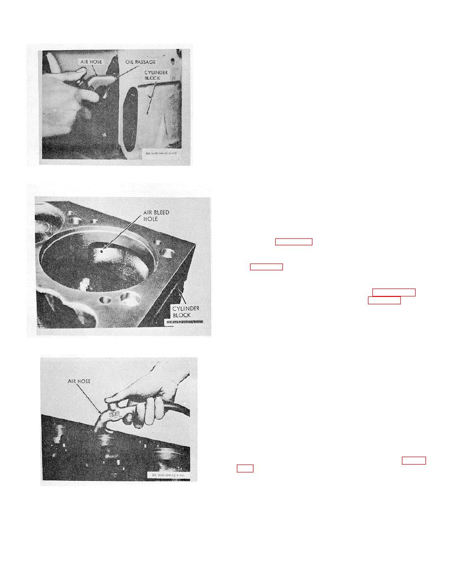
Figure 3-234. Cleaning block oil passages.
they are open.
(4) Inspect for eroded water holes which
may prevent proper seating of head gasket or grommet
retainers. Water holes not eroded more than 1/16 inch
from edge of hole can be reamed and bushings inserted.
(5) Use inside micrometer or dial bore gage
to gage camshaft bushing inside diameter as illustrated
in figure 3237. Replace bushings if worn larger than limit
shown in table 2-2. If bushings have been badly
chipped, scored or scratched, mark for replacement. If
bushings have turned in block bore, check block size;
see table 2-2.
(6) Check upper cylinder liner counterbore
diameter A, at four equidistant points around the
circumference of the liner as illustrated in figure 3-238.
If counterbore exceeds limits shown in table 2-2 for the
top 0.250 inch depth, the block will have to be machined
for oversize flange liners (e.(4)). The counterbore ledge
must be smooth and perpendicular to the cylinder liner
bore.
Figure 3-235. Air bleed hole.
(7) Check counterbore depth B so installed
liner will be assembled to correct protrusion and to
determine if refinish of counterbore surface is necessary.
Depth of counterbore on a new block is listed in table 2-
2. If worn to or beyond worn limit the cylinder block must
be replaced.
(8) Installed cylinder liners must protrude
0.004/0.006 in. above block. To check for proper
protrusion without installing a liner:
(a) Measure liner flange outside bead with
micrometer (fig. 3239).
Note. Do not include bead on top of liner flanog in
taking measurement.
(b) Measure block counterbore depth with
dial indicator depth gage or ST-547 Gage Block (fig. 3-
measurement.
(c)
Inspect depth at four equidistant
Figure 3-236. Cleaning cylinder head capscrew holes.
locations.
(9) Clean lower liner bore with sandpaper or
3-84


