
SECTION II
CONTROLS AND OPERATION
4. TACHOMETER-HOURMETER. This gauge indicates
the engine speed in revolutions per minute (RPM) and
the total number of hours the engine has been run.
5. L. H. DIRECTIONAL SIGNAL INDICATOR
6. HEATER CONTROLS. This switch controls the
heater fan. Turn the switch clockwise to energize the
heater fan; control the speed of the fan by turning the
switch clockwise or counterclockwise as desired.
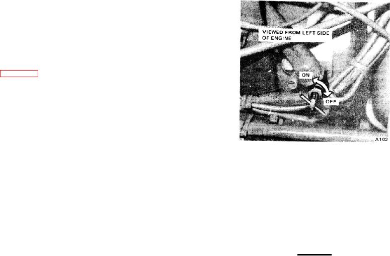
Figure 2-3 illustrates the heater shut off valve. Turn the
valve clockwise to stop the flow of water through the
heater, when heat is not required. Turn the valve
counterclockwise when heat is desired.
7. ENGINE STOP BUTTON (G.M. ENGINES ONLY).
Depress this button to stop the engine. After the engine
has stopped, place the ignition key in the OFF position.
8.
DEFOGGER FAN SWITCH.
Turn the switch
clockwise to energize the defogger fan; control the speed
of the fan by turning the switch clockwise or
Figure 2-3. Heater Shut-Off Valve
counterclockwise as desired.
9. DIRECTIONAL SIGNAL LEVER. This lever
15. DIFFERENTIAL LOCKOUT CONTROL. This lever
actuates the directional signal lamps at the front and rear
locks and unlocks the interaxle differential. Place the
of the carrier. Pull the lever toward the operator to
lever in the LOCK position when approaching or
actuate the left directional signal; push the lever away
anticipating icy or poor tractive conditions. This will
from the operator to actuate the right directional signal.
provide maximum axle traction. The interaxle differential
10. HAZARD WARNING INDICATOR. This lamp, when
can be shifted to the locked position at any vehicle
illuminated, indicates that all the directional lights are
speed, except if the wheels have already lost traction
energized for use as hazard warning lights.
and are spinning.
11. HORN BUTTON. Depress this button to sound the
carrier horn.
CAUTION
12. STEERING WHEEL.
Do not wait until you have lost
NOTE
traction and our Do not wait until
you have lost traction and your
If the machine is equipped with a
wheels are spinning to lock the
Power Steering/ Outrigger Selector
interaxle differential.
This could
Valve (item 25), be sure it is pushed
result in damage to the axles.
in and latched when operating the
carrier.
Place the lever in the UNLOCK position after passing
adverse' conditions.
This permits the interaxle
13. HAZARD WARNING LIGHT SWITCH. Push this
differential to compensate for differences in the tire size
switch away from the operator to energize all directional
and give you maximum speed and performance.
lights for use as hazard warning lights.
14. WINDSHIELD WIPER SWITCH. Turn this switch
NOTE
clockwise to energize the windshield wiper; control the
speed of the wiper by turning the switch clockwise or
Let up on the accelerator to provide
counterclockwise as desired.
an interruption in torque to the drive
train when locking or unlocking the
interaxle differential.
16. EMERGENCY RELEASE VALVE. The emergency
release valve provides a means of transferring the
isolated emergency air tank to the Maxibrake control
valve (item 17) when pressure in the service tanks is
lost.
1-2-3