
SUB-SECTION 5J
WINCHES
7. This should normally complete the disassembly of the
secondary drive. However, if complete disassembly is re-
quired including the drum bearings and seals, refer to
Figure 5J-15 and remove the housing spacer and inner ring
gear. Then, block the winch drum so that it cannot drop,
remove the mounting plate (Figure 5J-16) capscrews and
lockwashers, and remove the mounting plate. The drum can
now be removed from its base for replacement of bearings
and seals as required. Note that the drum sleeve is pressed
into the drum and cannot be removed until the mounting
plate is removed.
REASSEMBLY OF FINAL DRIVE. In general, reassembly
is the reverse of disassembly. Only where an adjustment or
a procedure is not the exact reverse of disassembly will
additional detail be given in the following reassembly
procedure. Reassemble from the final drive end as follows:
NOTE
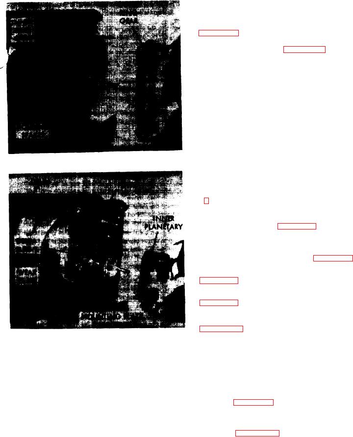
Figure 5J-15. Removing Outer Ring Gear
When the drum has been installed in the side stand,
production tolerances will allow 0.018 to 0.069 inch
(0.46-1.75 mm) drum end play.
1 Refer to Figure 5J-16, reinstall the mounting plate and
secure with mounting plate capscrews. If they have been
removed, reinstall the three guide studs and install the inner
ring gear and housing ring (Figure 5J-15) on the studs. Press
the ring gear and housing ring firmly against the mounting
plate.
2. Install the inner planetary assembly (Figure 5J-16).
3. Install the outer ring gear in the position shown in
4. Install the outer planetary in the position shown in
5. Place the end cover on the guide studs as shown in
Figure 5J-12 and install two end cover capscrews 180
degrees apart. Remove the three guide studs and install the
Figure 6J-16. Removing Inner Planetary Assembly
rest of the eight end cover capscrews. Then tighten the end
plate capscrews to 55 foot pounds (7.6 m-kg) lubricated or
75 foot pounds (10.4 m-kg) dry torque, being sure to
bad or if a roll pin has sheared, the damage will be so
tighten in the approved cross bolting sequence. That is,
extensive that it is advisable to order a complete replace-
tighten two capscrews 180 degrees apart, then two more at
ment assembly.
right angles to the first pair, and so on.
5. Loosen and remove the outer ring par as shown in
6. Refer to Figure 5J-11, remove the breather cap, and fill
Figure 5J-15. Inspect the gear teeth for excessive wear.
with 1/2 gallon (1.9 I) of SAE 90 transmission oil to the
Original backlash was 0.004 to 0.008 inch (0.10-0.20 mm)
level of the level plug.
per gear sat. Note that the proper criterion for replacement
is basically "does it work?". Replace only if absolutely
7. Refer to Figure 5J-17 and install the drum shaft as
necessary.
shown. Note that the shaft has a smaller outer diameter for
about four inches (10.2 cm) on the end being inserted. This
6. Remove the inner planetary as shown in Figure 5J-16.
end of the shaft must be installed as shown. It will be nec-
Inspect this planetary assembly in the same manner des-
essary to align the shaft splines with the outer planetary sun
cribed for the outer assembly. lnspect the wear plates
gear by feel. Be sure the shaft is fully entered into the outer
shown in Figure 5J.16 and replace if wear patterns are
planetary.
evident.
5J-7