TM 5-3810-294-34
1.
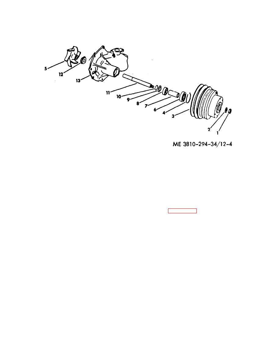
Nut
8.
Bearing
2.
Washer
9.
Slinger
3.
Pulley
10.
Lock ring
4.
Retaining ring
11.
Shaft
5.
Impeller
12.
Seal
6.
Bearing
13.
Body
7.
Spacer
Figure 12-4. Water pump, exploded view
a. Remove nut (1), washer (2) and press pulley (3)
12-20. Reassembly and Installation
off shaft.
Refer to figure 12-4 and reassemble the pump as
b. Remove retaining ring (4).
follows:
c. Set the pump on an arbor press and press the
a. Press a new seal (12) into body (13).
shaft and bearings as a unit out of the impeller (5).
b. Pack bearings with grease and install bearing
d. Press off the bearing (6), spacer (7), bearing (8),
(8), spacer (7) and bearing (6) on shaft (11) Place slinger
slinger (9), and lock rings (10). Be careful not to lose the
(9) in position.
half rings.
c. Place two lock rings (10) in groove of shaft and
e. Use a drift pin and drive the seal (12) out of body
press shaft toward pulley end into bearings until bearing
(13).
(8) rests firmly against slinger (9) I and lock rings (10).
d. Fill cavity with 11/2 ounces of short fiber bearing
12-18. Cleaning Wash all metal parts with dry cleaning
grease. Install shaft and bearing assembly into body and
secure with retaining ring (4).
solvent 1Federal Specification P-S-661) and dry with
e. Press pulley (3) onto shaft and secure with
compressed air.
washer (2) and nut (1).
f. Press impeller (5) onto shaft until axial distance
12-19.
Inspection and Repair
from mounting surface of pump, body to end of impeller
a.
Replace seal if it is worn, corroded or damaged.
is 1 1/ 16 inches.
b.
Replace bearings if worn or corroded
g. Install water pump on engine as instructed in TM
c.
Replace shaft if worn at the ends.
5-3810-294-20.
d.
Replace all parts with worn or damaged threads.
12-9


