TM 5-3810-295-34
2-20. Control Stand Assembly
a.
Removal
(1) Refer to TM 5-3810-295-12 and shut off the hydraulic oil supply to the control sand assembly.
(2) Refer to figure 2-1 and remove plates and floor plates as required to se the control stand assembly.
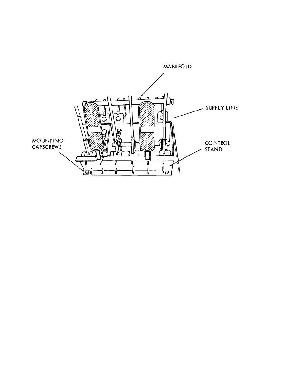
(3) Refer to figure 2-15 and remove the control stand assembly.
STEP 1. DISCONNECT SUPPLY LINE AT MANIFOLD AND ALL MASTER CYLINDER OUTPUT LINES. PLUG LINES.
STEP 2. REMOVE MOUNTING CAPSCREWS.
STEP 3. REMOVE CONTROL STAND.
TA033160
Figure 2-15. Control stand assembly, removal and installation.
2-40 Change 1


