TM 5-3810-295-34
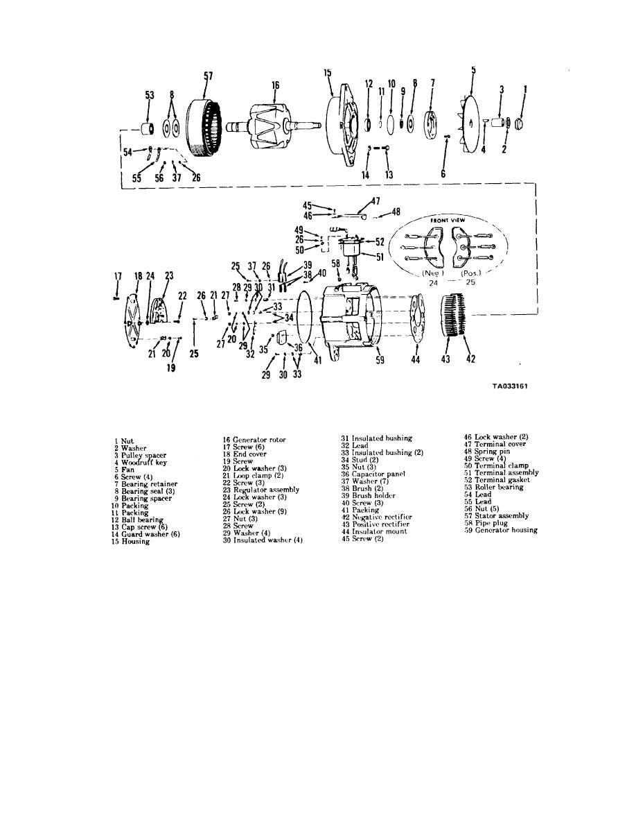
Figure 3-1. Generator assembly-exploded view.
f.
Remove screw (19), lock washer (20) and loop clamp (21) from the end plate cover. Remove screws (22),
regulator (23) and lock washers (24).
g. Remove screw (25), lock washer (26) and loop clamp (21). Remove nut (27), screw (28), washers (29) and
(20), insulated washers (30), insulated bushing (31), lead (32), insulated bushing (33), and studs (34).
h. Remove capacitor panel (36) by removing nuts
35). Remove brushes (38) and brush holder (39) by
removing screw (25), washer (37) and lock washer (26).
i.
Remove screws (40), washers (29) and insulated washer (30), and insulated bushing (33). Remove packing
(41).
j.
Remove rectifiers (42) and (43) from insulator mount (44).
k. Remove screws (45), lock washers (46) and lift ter-
3-2


