TM 5-3810-295-34
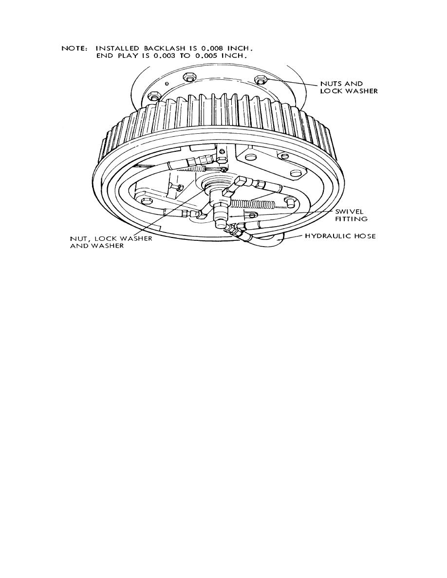
STEP 1.
DISCONNECT HYDRAULIC HOSE AT SWIVEL. PLUG HOSE AND SHAFT HOLE IMMEDIATELY.
STEP 2.
REMOVE SWIVEL BY UNSCREWING FROM SHAFT.
STEP 3.
REMOVE CLUTCH MOUNTING NUTS, LOCKWASHERS, AND WASHERS. REMOVE CLUTCH AS A UNIT.
STEP 4.
SUPPORT ASSEMBLY WITH A SUITABLE LIFTING DEVICE. REMOVE SHAFT NUTS AND LOCK
WASHERS.
STEP 5. REMOVE HORIZONTAL SWING SHAFT ASSEMBLY.
Figure 2-8. Horizontal swing shaft assembly, removal and installation
b.
Installation
(1) Refer to figure 2-7 and install reversing shaft.
(2) Refer to TM 5-3810-295-12 and perform the following operations:
(a) Install reversing shaft chain and adjust chain tension by means of the chain idler.
(b) Open hydraulic reservoir shut-off valve. Bleed hydraulic line to the reversing shaft.
2-15.
Horizontal Swing Shaft Assemblies
a. General Two horizontal swing shafts are used. Each shaft drives the upper in one direction only. The left
shaft drives the upper to the right. The right shaft drives the upper to the left. Be sure the correct shaft is removed in the
event of swing system malfunction.
b. Removal
(1) Refer to TM 5-3810-295-12 and perform the
2-29


