
TM 5-3810-300-24&P-3
Main Bearings 1.3.4
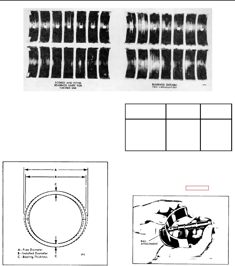
Fig. 5. Comparison of Main Bearing Shells
micrometer, will give an accurate measurement. The
Bearing
Bearing
Minimum
bearing shell thickness will be the total thickness of the
Size
Thickness
Thickness
steel ball in the tool and the bearing shell, less the
diameter of the ball. This is the only practical method for
Standard
.1548"/.1553"
.1530"
measuring the bearing thickness, unless a special
.002" Undersize
.1558"/.1563"
.1540"
micrometer is available for this purpose. The minimum
.010" Undersize
.1598"/.1603"
.1580"
thickness of a worn standard main bearing shell is .1530"
.020" Undersize
.1648"/.1653"
.1630"
and, if any of the bearing shells are thinner than this
.030" Undersize
.1698"/.1703"
.1680"
dimension, replace all of the bearing shells. A new
standard bearing shell has a thickness of .1548" to
TABLE 1
.1553". Refer to Table 1.
In addition to the thickness measurement, check the
clearance between the main bearings and the crankshaft
journals. This clearance may be determined with the
crankshaft in place by means of a soft plastic measuring
strip which is squeezed between the journal and the
bearing (refer to Shop Notes in Section 1.0).
Fig. 7. Measuring Thickness of Bearing Shell
Fig. 6. Main Bearing Measurements
PAGE 74