SUBSECTION 5D
HYDRAULIC COMPONENTS
CAPSCREW
01.
02.
BODY CAP
03.
LOCK WIRE
*04.
ROD WIPER
ROD SEAL
*05.
06.
HEAD GLAND
*07.
BACK-UP RING
*08.
O-RING
*09.
PISTON SEAL
10.
PISTON
*11.
PISTON SEAL
*12.
O-RING
13.
LOCKNUT
14.
ROD
*PARTS CONTAINED IN SEAL KIT.
BODY
15.
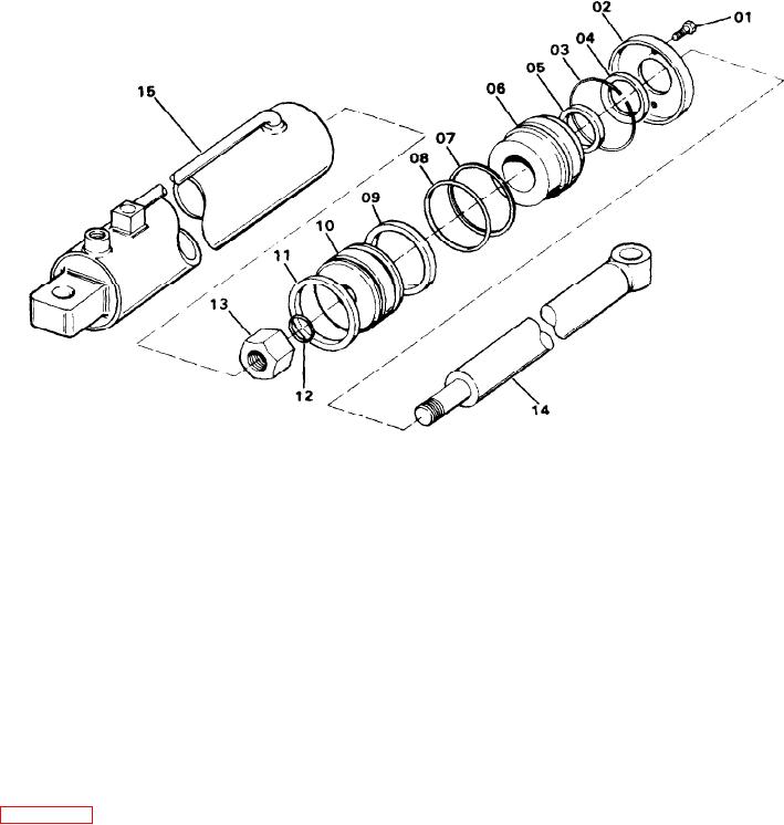
Figure 5D-6. Crawler Extension Cylinder (38U113)
7. Install O-ring (12) in the groove of rod (14) and insert
3. Pull the complete rod, head gland and piston from the
piston (10) to the shoulder of the rod. Then, tighten locknut
body of the cylinde.
(13) securely.
4. Remove locknut (13) from rod (14) and slide off piston
8. Carefully insert the assembled unit into the bore of the
(10) and head gland (06).
cylinder. Compress the seals as necessary to prevent them
5. Remove aII the seaIs from piston (10) and head gland (06)
from being damaged.
and discard.
9. Push the head gland into the bore and install the lock
INSPECTION AND REPAIR Clean all the parts with a suit-
wire.
able solvent and inspect the rod, piston, head gland and cyl-
10. Pull out on the rod to move the head gland into posi-
inder bore for excessive wear, nicks, or scratches. If any of
tion, then install the capscrews and tighten securely.
these parts are damaged, the part(s) may be replaced as in-
dicated in the Parts Manual.
INSTALLATION. To Install the crawler extension cylinder,
proceed as follows:
ASSEMBLY. To assemble the cylinder, proceed as follows
(see Figure 5D-6):
1. Place the head end of the cylinder in the bracket on the
carbody and insert the pin. Mount the rod end on a support
1. Coat all parts with clean hydraulic oil.
to provide free movement in and out.
2. Install O-ring (08) and back-up ring (07) in the groove of
2. Connect the hydraulic line for extending the cylinder
head gland (06). The back-up ring is located nearest lock
first.
ring (03).
3. Place rod seal (05) into the inside head gland groove with
NOTE
the lips of the seal facing O-ring (08) groove.
The extend port is the one nearest the head end of the
cylinder.
4. Seal (04) is placed in the outside groove of the grooves of
piston (10) with the lips facing the rod end of the cylinder.
3. Connect the battery ground and start the engine.
Gradually operate the control valve to fill the head end of the
5. Assemble piston seals (09 and 11) into the grooves of
cylinder with hydraulic oil.
piston (10) with the lips of both seals facing the outside of
the piston.
4. With the rod fully extended, connect the other hydraulic
line and operate the control valve to fully retract the rod.
6. Slide body cap (02), lock wire (03) and head gland (06)
Cycle the cylinder several times to remove any air trapped.
onto rod (14).
5D-10

