
to another. If this is done it could
result in permanent damage to the
tool.
C. Install scrap or dummy injectors to
ensure proper seating of the injector
tubes. Dummy injectors may be made
from oil injector nuts and bodies; the
injector spray tips are not necessary.
Tighten the injector clamp to 20-25
lb-ft (27-34 Nm) torque.
D. Apply 40 psi (276 kPa) air pressure
to the water jacket. Then immerse
the cylinder head in a tank of water,
previously heated to 180-2OOF
(82-93C), for about twenty minutes
to thoroughly heat the head. Ob-
serve
the
water
in
the
tank
for
bubbles
which
indicate
a
leak
or
crack.
Check
for
leaks
at
the
top
and bottom of the injector tubes, oil
gallery, exhaust ports, fuel manifolds
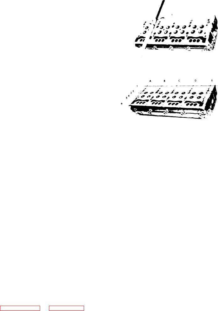
F i g u r e 11B-31. Checking Bottom Face
and the top and bottom of the cylin-
of Cylinder Head
der head.
NOTE
E. Relieve the air pressure and remove
the cylinder head from the water
When a cylinder head has been re-
tank. Then remove the plates, gas-
faced, critical dimensions such as
kets and injectors and dry the head
the protrusion of valve seat in-
with compressed air.
serts, exhaust valves, injector
tubes and injector spray tips must
2. Check the bottom (fire deck) of the
be checked and corrected. the
cylinder head for flatness:
push rods must also be adjusted to
prevent the exhaust valves from
A. Use a heavy, accurate straight edge
striking the pistons after the cyl-
and feeler gauges, tool J 3172, to
inder head is reinstalled on the
check for transverse warpage at each
engine.
end and between all cylinders. Also
check for longitudinal warpage in six
places as shown in Figure 11B-31.
3. Install new injector tubes if the old
The maximum allowable transverse
tubes leaked or the cylinder head was
warpage is 0.004"; longitudinal war-
refaced.
p a g e is 0.008".
4. Inspect the exhaust valve seat inserts
B. Use the measurement obtained and the
and valve guides.
limits given in step A as a guide to
determine the advisability of reinstal-
5. Inspect the cam follower bores in the
ling the head on the engine or of re-
cylinder head for scoring or wear. L i g h t
The number of times a
facing it.
score marks may be cleaned up with cro-
cylinder head may be refaced will de-
cus cloth wet with fuel oil. Measure the
pend
upon
the
amount
of
stock
bore diameters with a telescope gauge
previously removed.
and micrometer and record the readings.
Measure the diameter of the cam followers
C. If the head is to be refaced, remove
with a micrometer. Record and compare
the injector tubes prior to machining.
the readings of the follower and bores to
do not remove more metal from the
determine the cam follower-to-bore clear-
fire deck of any cylinder head below
ances. The clearances must not exceed
the minimum distance of 3.356" (see
0.006" with used parts. If the bores are
excessively scored or worn, replace the
cylinder head.