TM5-3810-305-10
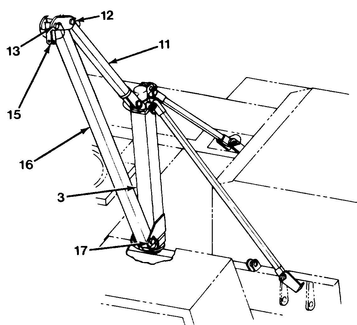
13. Install lift arm (16) as follows:
a.
b.
c.
d.
With lift arm (16) still in storage location
B on right side of boom, pull out sheave
pin (13) and remove sheave (14) from
sheave bracket (15, Figure 5-11 ).
Temporarily lay sheave (14) aside.
Weight of the lift arm is
approximately 95 lb (43 kg).
Use two people to properly
support and lift the lift arm.
Failure to follow this procedure
could cause DEATH or serious
injury.
Remove lift arm (16) and pins (17) and
(18) from storage brackets. Place pin (18)
in tool box for future use.
With sheave bracket (15) down, connect
lift arm (16) to base of mast (3) with pin
(17, Figure 5-12).
e.
f.
Using two pins (12), attach adjustable
truss rod (11) to top of mast (3) and top of
lift arm (16). The mast and arm assembly
is now complete.
Temporarily swing mast and arm assembly
out of the way.
14. Start engine. Raise boom until a minimum
boom angle of 45 degrees is observed on
boom angle indicator.
15. Shut engine off.
The crane winch is used to hoist and separate
upperstructure from carrier. Extension hoses are
added to winch hydraulic circuit, supplying
power to winch to hoist upperstructure off carrier
and lower it to ground.
The rotary manifold is located internally in
center of upperstructure. Access to rotary mani-
fold is through opening under boom and through
cutout on sides of upperstructure.
Figure 5-12. Assembling the Mast
5-9


