
TM 5-3810-305-23
0062
INSTALLATION
1.
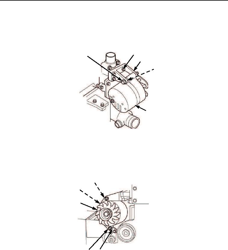
Install support (Figure 3, Item 3) and three capscrews (Figure 3, Item 2) on engine.
2.
Install spacer (Figure 3, Item 4), alternator (Figure 3, Item 5) and mounting capscrew (Figure 3, Item 1)
on support (Figure 3, Item 3). Do not tighten capscrew at this time.
2
1
3
4
5
M0103105
Figure 3. Alternator and Mounting Bracket Assembly Installation.
3.
Install brace (Figure 4, Item 3) and two capscrews (Figure 4, Item 4) at lower end of alternator
(Figure 4, Item 5). Tighten two capscrews to 18 ft-lb (24 Nm).
4.
Tighten mounting capscrew (Figure 3, Item 1) to 32 ft-lb (43 Nm).
5.
Connect wires (Figure 4, Items 1 and 2) to alternator (Figure 4, Item 5).
2
1
5
4
M0102105
3
Figure 4. Alternator and Mounting Bracket Assembly Installation.
END OF TASK
03/15/2011Rel(1.8)root(maintwp)wpno(M00068)