
9
0
8
2
3
6
1
4
7
5
,
TM 5-3810-305-23
0066
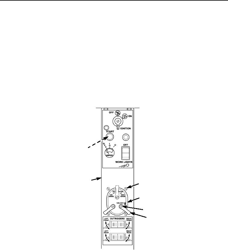
REMOVAL - Continued
Side Sloping Dash Panel - Continued
NOTE
Tag wires to aid installation.
9.
Remove three screws (Figure 9, Item 4), three levers (Figure 9, Item 5), and four screws (Figure 9, Item 1).
Push switch (Figure 9, Item 2) down through sloping dash panel (Figure 9, Item 6).
10.
Disconnect wires (Figure 9, Item 3) from master light switch (Figure 9, Item 2).
11.
Disconnect wires (Figure 9, Item 8) from back of start button (Figure 9, Item 7).
12.
Loosen nut (Figure 9, Item 9) on back of start button (Figure 9, Item 7) and unscrew rubber cover
(Figure 9, Item 10).
13.
Push start button (Figure 9, Item 7) out through rear of sloping dash panel (Figure 9, Item 6).
M0508105
Figure 9. Side Sloping Dash Panel Removal.
03/15/2011Rel(1.8)root(maintwp)wpno(M00072)