TM 5-3810-305-23
0102
REMOVAL - Continued
10.
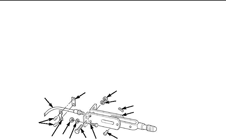
Remove two nuts (Figure 5, Item 3), lockwashers (Figure 5, Item 4), capscrews (Figure 5, Item 9), spacer
(Figure 5, Item 2), clamp (Figure 5, Item 12), and two spacers (Figure 5, Item 13) from cable
(Figure 5, Item 1) mounted to lever (Figure 5, Item 6). Discard lockwashers.
11.
Remove cotter pin (Figure 5, Item 5) and pin (Figure 5, Item 7) to release cable (Figure 5, Item 1) from lever
(Figure 5, Item 6). Discard cotter pin.
12.
Remove cable (Figure 5, Item 1) by pulling out of cab.
13.
Remove four nuts (Figure 5, Item 11) and lockwashers (Figure 5, Item 10) from rear of cab.
Discard lockwashers.
14.
Remove four capscrews (Figure 5, Item 8) inside cab to remove lever (Figure 5, Item 6).
3
2
1
4
5
6
13
11
12
7
9
10
8
M0532105
Figure 5. Parking Brake Removal.
END OF TASK
DISASSEMBLY
1.
Remove cotter pin (Figure 6, Item 13), castle nut (Figure 6, Item 12), and washer (Figure 6, Item 14) from stud
in cam side casting (Figure 6, Item 5). Discard cotter pin.
2.
Remove operating cam (Figure 6, Item 11) from stud in cam side casting (Figure 6, Item 5).
3.
Remove two springs (Figure 6, Item 4) and spring (Figure 6, Item 7) from side casting (Figure 6, Item 5) and
carrier casting (Figure 6, Item 6).
4.
Remove two pad holder assemblies (Figure 6, Item 8) from side casting (Figure 6, Item 5) and carrier casting
(Figure 6, Item 6).
5.
Remove two bolts (Figure 6, Item 1), washers (Figure 6, Item 2), and bracket (Figure 6, Item 3) from side
casting (Figure 6, Item 5).
6.
Remove bolt (Figure 6, Item 15) and washer (Figure 6, Item 9) to separate cam side casting (Figure 6, Item 5)
and carrier casting (Figure 6, Item 6).
7.
Remove two push pins (Figure 6, Item 10) from cam side casting (Figure 6, Item 5).
03/15/2011Rel(1.8)root(maintwp)wpno(M00113)

