TM 5-3810-305-23
0102
INSTALLATION - Continued
6.
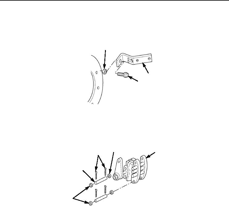
Install sensor (Figure 10, Item 3) on bracket (Figure 10, Item 2) with jam nut (Figure 10, Item 1). Adjust sensor.
7.
Connect wiring harness to sensor (Figure 10, Item 3). Note tag from removal.
1
2
3
M0530105
Figure 10. Parking Brake Installation.
8.
Position caliper assembly (Figure 11, Item 4) on front axle.
9.
Apply grease to two mounting pins (Figure 11, Item 1). Install mounting pins, four washers (Figure 11, Item 3),
and new cotter pins (Figure 11, Item 2), securing caliper assembly (Figure 11, Item 4) to front axle.
3
4
2
1
3
M0534105
Figure 11. Parking Brake Installation.
10.
Install clamp (Figure 12, Item 8), two capscrews (Figure 12, Item 9), new lockwashers (Figure 12, Item 4),
and nuts (Figure 12, Item 5) to secure cable (Figure 12, Item 7) to bracket (Figure 12, Item 6).
11.
Install spring (Figure 12, Item 10), new lockwasher (Figure 12, Item 12), nut (Figure 12, Item 11), and yoke
(Figure 12, Item 13) on end of cable (Figure 12, Item 7).
12.
Install pin (Figure 12, Item 1) and new cotter pin (Figure 12, Item 2) in caliper assembly (Figure 12, Item 3).
13.
Check cable (Figure 12, Item 7) for correct adjustment and ease of movement.
03/15/2011Rel(1.8)root(maintwp)wpno(M00113)

