TM 5-3810-305-23
0109
ASSEMBLY - Continued
9.
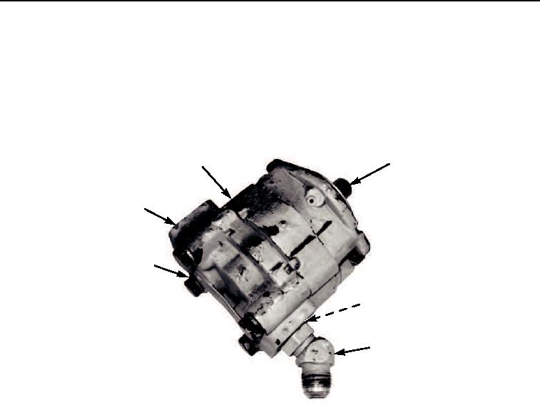
Align matchmarks and install rear flange plate (Figure 15, Item 7) on gear plate (Figure 15, Item 1).
10.
Install four washers (Figure 15, Item 6) and capscrews (Figure 15, Item 5) on pump. Torque capscrews
to 35 ft-lb (47 Nm).
11.
Install new o-ring (Figure 15, Item 3) and elbow (Figure 15, Item 4).
12.
Coat splines of pump (Figure 15, Item 2) with antiseize thread compound.
1
2
7
5,6
3
4
M0438105
Figure 15. Ground Driven Steering Pump Assembly.
END OF TASK
INSTALLATION
1.
Apply threadlock compound to pump mounting flange.
2.
Apply threadlock compound to two capscrews (Figure 16, Item 4).
3.
Position pump (Figure 16, Item 12) on transmission (Figure 16, Item 3) and install two new lockwashers
(Figure 16, Item 5) and capscrews (Figure 16, Item 4).
4.
Install hose (Figure 16, Item 1) on elbow (Figure 16, Item 2).
5.
Install new o-ring (Figure 16, Item 11) on adapter (Figure 16, Item 10).
6.
Position adapter (Figure 16, Item 10) on pump (Figure 16, Item 12) and install four new lockwashers
(Figure 16, Item 9) and capscrews (Figure 16, Item 8).
7.
Install hose (Figure 16, Item 6) on adapter (Figure 16, Item 10) and tighten clamp (Figure 16, Item 7).
03/15/2011Rel(1.8)root(maintwp)wpno(M00122)

