
TM 5-3810-305-23
0125
ASSEMBLY - Continued
CAUTION
Be certain snapring is seated in groove in splined bore of cam. Snapring will keep brake clutch
assembly correctly positioned in center of friction brake pack. Binding of brake or brake failure
may occur if snapring is omitted.
NOTE
When installed correctly, cam should turn freely in opposite direction drum turns
to pull wire rope in. An easy way to check rotation is to hold outer race in one hand,
and rotate cam.
If brake discs are misaligned, preventing installation of clutch, use a hand pump to
apply 750 to 1,000 psi (5,171 to 6,895 kPa) to brake release port adapter. Brake discs
will move freely with brake released, permitting alignment of discs, brake clutch and sun
primary gear.
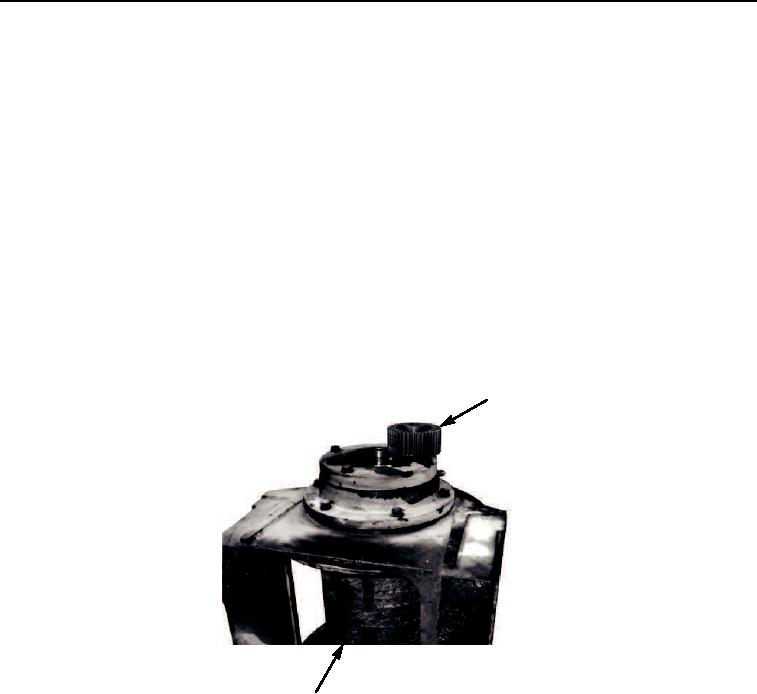
23.
Install brake clutch assembly (Figure 28, Item 1) into drum (Figure 28, Item 2).
1
2
M0675105
Figure 28. Brake Clutch Assembly Assembly.
03/15/2011Rel(1.8)root(maintwp)wpno(M00141)