
TM 5-3810-305-23
0125
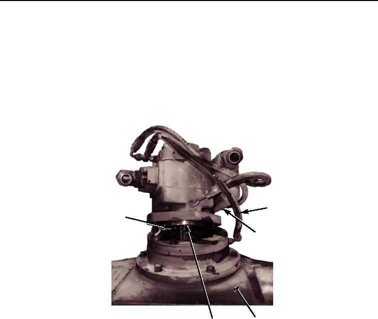
ASSEMBLY - Continued
24.
Lubricate new o-ring (Figure 29, Item 1) with lubricating oil.
25.
Install new o-ring (Figure 29, Item 1) on pilot of motor (Figure 29, Item 6).
26.
Install motor, engaging motor shaft with brake clutch cam and lower motor into drum.
27.
Install two new lockwashers (Figure 29, Item 4) and capscrews (Figure 29, Item 3).
28.
Connect hose (Figure 29, Item 2) to winch (Figure 29, Item 5).
2
1
3,4
5
6
M0676105
Figure 29. Motor Installation Assembly.
03/15/2011Rel(1.8)root(maintwp)wpno(M00141)