TM 5-3810-305-23
0126
ASSEMBLY - Continued
16.
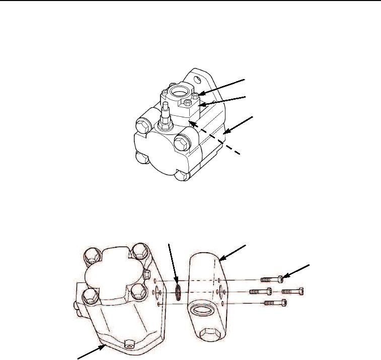
Install new o-ring (Figure 26, Item 4) and split flange adapter (Figure 26, Item 2) on motor (Figure 26, Item 3)
with four allen screws (Figure 26, Item 1).
1
2
3
4
M0627105
Figure 26.
Winch Motor Assembly.
17.
Install new o-ring (Figure 27, Item 1), winch brake valve assembly (Figure 27, Item 2), and four allen screws
(Figure 27, Item 3) on motor (Figure 27, Item 4).
1
2
3
4
M0626105
Figure 27.
Winch Motor Assembly.
03/15/2011Rel(1.8)root(maintwp)wpno(M00143)

