• Home
  • Download PDF
  • Order CD-ROM
  • Order in Print
Figure 9. Rotary Manifold Installation.
Figure 11. Rotary Manifold Installation.

Technical Manual For Crane, Wheel Mounted, Hydraulic, Light, 7 1/2 Ton Page Navigation
  905    906    907    908    909  910  911    912    913    914    915  
img
.
TM 5-3810-305-23
0135
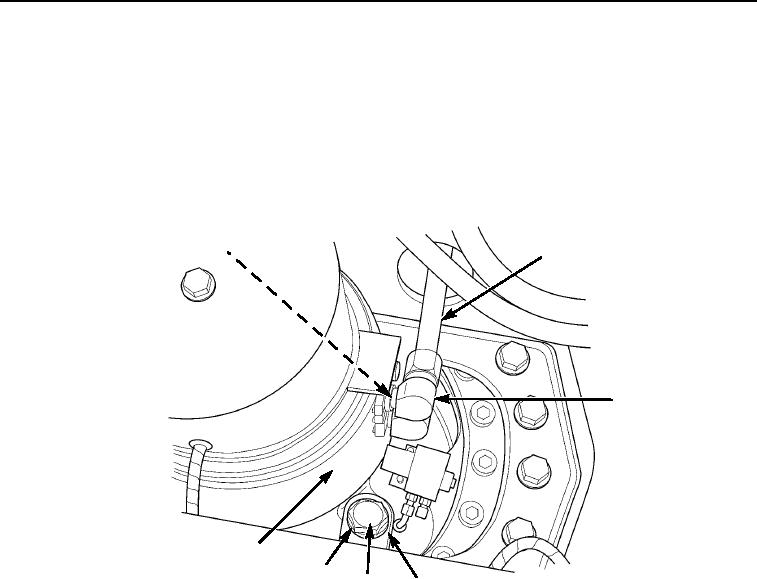
INSTALLATION - Continued
NOTE
Install elbows as tagged during removal.
8.
Install six new o-rings (Figure 10, Item 1) and elbows (Figure 10, Item 3) to side of manifold
(Figure 10, Item 7).
9.
Connect six hoses (Figure 10, Item 2) to side of manifold (Figure 10, Item 7).
1
2
3
7
6
5
4
M0455105
Figure 10. Rotary Manifold Installation.
0135-13
03/15/2011Rel(1.8)root(maintwp)wpno(M00151)


Privacy Statement
Press Release
Contact

© Copyright Integrated Publishing, Inc.. All Rights Reserved.