TM 5-3810-305-23
0140
INSTALLATION
1.
Install two adapters (Figure 2, Item 5) and hoses (Figure 2, Item 13) with flex trim (Figure 2, Item 14).
2.
Connect two hoses (Figure 2, Item 13) to rotary manifold.
3.
Install five clamps (Figure 2, Item 2), five washers (Figure 2, Items 3 and 15), and five new
locknuts (Figure 2, Item 8).
4.
Install two tubes (Figure 2, Item 1) to elbows.
5.
Install two hoses (Figure 2, Item 9) with flex trim (Figure 2, Item 14) to tubes (Figure 2, Item 1).
6.
Connect two hoses (Figure 2, Item 9) to rotary manifold.
7.
Install two clamps (Figure 2, Item 4), two washers (Figure 2, Items 6 and 7), and two new locknuts
(Figure 2, Item 7) to hose (Figure 2, Item 9).
8.
Install two tubes (Figure 2, Item 10) to rotary manifold.
9.
Connect hoses (Figure 2, Items 11 and 12) to two tubes (Figure 2, Item 10).
10.
Connect hoses (Figure 2, Items 11 and 12) to winch.
11.
Install eight clamps (Figure 2, Item 7), two plates (Figure 2, Item 15), and six capscrews (Figure 2, Item 18).
WARNING
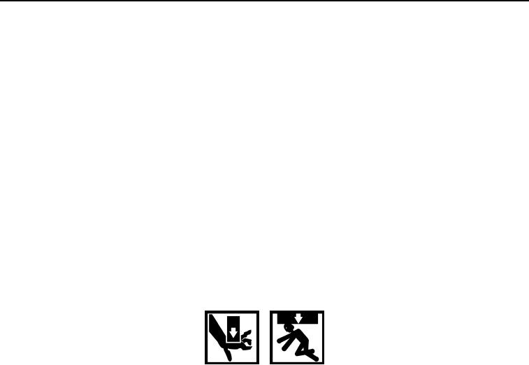
Weight of boom is approximately 3,100 lb (1,406 kg). Use adequate lifting equipment to lift
and support boom. DO NOT lift over personnel or let personnel walk underneath suspended
load. Failure to follow this warning may cause injury or death to personnel.
12.
Return boom to travel position (TM 5-3810-305-10).
0140-4
03/15/2011Rel(1.8)root(maintwp)wpno(M00157)

