
TM 5-3810-305-23
0146
CLEANING
Clean parts IAW General Maintenance Instructions (WP 0162).
END OF TASK
INSPECTION
Inspect parts IAW General Maintenance Instructions (WP 0162).
END OF TASK
INSTALLATION
1.
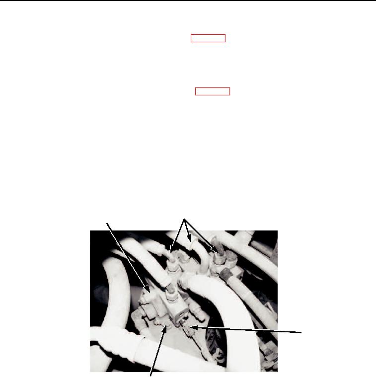
Position control valve (Figure 2, Item 1) on frame location.
2.
Install three capscrews (Figure 2, Item 4), new lockwashers (Figure 2, Item 5) and nuts (Figure 2, Item 6)
on control valve (Figure 2, Item 1).
3.
Connect four control cables and disconnect assemblies (Figure 2, Item 3).
4.
Install 14 fittings and connect hoses (Figure 2, Item 2) to control valve (Figure 2, Item 1).
2
1
3
LRT110--2378
LRT110 2378
4,5,6
M0340105
Figure 2. Hydraulic System Valve Bank Installation.
END OF TASK
03/15/2011Rel(1.8)root(maintwp)wpno(M00163)