TM 5-3810-305-23
0145
INSTALLATION - Continued
8.
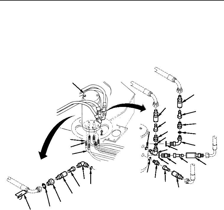
Install new o-rings (Figure 8, Items 5, 11 and 15) onto fittings (Figure 8, Items 4, 10 and 19).
9.
Install new o-rings (Figure 8, Items 7 and 15) onto elbows (Figure 8, Items 6 and 16).
10.
Install six quick disconnects (Figure 8, Items 2, 8, and 18) and fittings (Figure 8, Items 3 and 9) to six hoses
on side of manifold (Figure 8, Item 1).
11.
Install six adapters (Figure 8, Item 14) and o-rings (Figure 8, Item 13) to bottom of manifold (Figure 8, Item 1).
Connect Six hoses (Figure 8, Item 12) to bottom of manifold.
1
2
2
3
3
4
7
4
5
5
14
6
13
6
7
12
9
8
11 10
11
10
16
9
15
17
8
18
19
15
20
M2111105
Figure 8. Rotary Manifold Quick Disconnects (Type II) Installation.
03/15/2011Rel(1.8)root(maintwp)wpno(M00162)

