
1
TM 5-3810-305-23
0147
ADJUSTMENT
1.
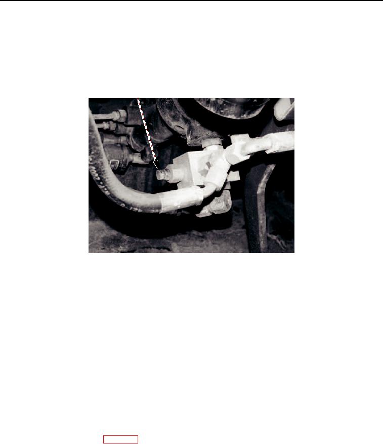
Remove dust cap (Figure 3, Item 1).
2.
Install a 0 to 4,000 psi (0 to 27,580 kPa) pressure gage on test port.
3.
Start engine. Run engine at full rpm (TM 5-3810-305-10).
M1551105
Figure 3. Relief Valve Adjustment.
NOTE
Valve setting is 2,500 +/- 50 psi (17,238 +/- 345 kPa) at full rpm.
4.
Hold steering wheel in full turn position long enough to get pressure reading. If pressure reading is correct, go
to Step 11. If not, continue procedure.
5.
Hold adjusting screw (Figure 4, Item 1) and loosen jam nut (Figure 4, Item 2).
6.
Hold steering wheel in full position and turn adjusting screw (Figure 4, Item 1) clockwise to increase pressure
or counterclockwise to decrease pressure until desired pressure setting is obtained.
7.
Hold adjusting screw (Figure 4, Item 1) and tighten jam nut (Figure 4, Item 2).
8.
Repeat Step 5.
9.
Shut engine OFF (TM 5-3810-305-10).
10.
Remove pressure gage from test port.
11.
Install dust cap on adjusting screw (Figure 4, Item 1).
12.
Install lower dash panel (WP 0110).
03/15/2011Rel(1.8)root(maintwp)wpno(M00185)