TM 5-3810-305-23
0149
INSTALLATION
1.
Install two new o-rings (Figure 13, Item 11) on adapters (Figure 13, Item 3). Position hold valve and four new
o-rings (Figure 13, Item 10) on boom hoist cylinder (Figure 13, Item 2) and install four new lockwashers
(Figure 13, Item 9), capscrews (Figure 13, Item 8), and two adapters.
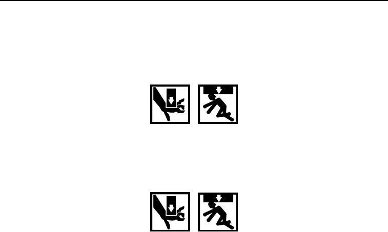
WARNING
Weight of boom is approximately 3,100 lb (1,406 kg). Use adequate lifting equipment to lift
and support boom. DO NOT lift over personnel or let personnel walk underneath suspended
load. Failure to follow this warning may cause injury or death to personnel.
2.
Raise boom to 30 degrees using suitable lifting equipment.
WARNING
Weight of boom hoist cylinder is approximately 507 lb (230 kg). Use adequate lifting
equipment to lift and support boom hoist cylinder. DO NOT lift over personnel or let personnel
walk underneath suspended load. Failure to follow this warning may cause injury or death to
personnel.
3.
Secure boom cylinder (Figure 13, Item 1) in suitable lifting device. Lift and position boom hoist cylinder
in upperstructure.
4.
Install pin (Figure 13, Item 7), rod (Figure 13, Item 6), new lockwasher (Figure 13, Item 5), and capscrew
(Figure 13, Item 4) cylinder end of boom hoist cylinder (Figure 13, Item 1).
5.
Apply threadlock sealant to hoses (Figure 13, Item 2) and adapters (Figure 13, Item 3).
6.
Install hoses (Figure 13, Item 2) to adapters (Figure 13, Item 3) at a 50 degree angle up from the long axis of
the boom hoist cylinder (Figure 13, Item 1).
0149-12
03/15/2011Rel(1.8)root(maintwp)wpno(M00165)

