
TM 5-3810-305-23
0150
DISASSEMBLY - Continued
3.
Pull rod assembly (Figure 2, Item 4) half way out of cylinder case (Figure 2, Item 1).
4.
Place support under outer end of rod assembly (Figure 2, Item 4).
CAUTION
Head gland should unscrew freely. If, after several turns, a bind is noticed, STOP: DO NOT
FORCE THREADS. Place a "C" clamp over threaded end of cylinder case in line with port
tube. Gradually draw down "C" clamp until head gland can be unscrewed easily. The reason
for an occasional bind is due to the fact that heat generated from welding of port tube to
cylinder case may cause a slight cylinder case eccentricity. This most generally occurs when
boom extend cylinder has been in service for only a short period of time. Extended service
stress relieves the weld and improves concentricity. This caution can be used in reassembly
if a bind occurs when installing head gland. Failure to follow this caution may result in damage
to equipment.
5.
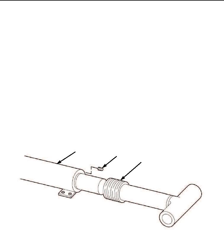
Remove setscrew (Figure 2, Item 2) from cylinder case (Figure 2, Item 1).
6.
Remove head gland (Figure 2, Item 3) from cylinder case (Figure 2, Item 1).
NOTE
Be sure head gland threads are fully disengaged from cylinder case threads.
7.
Pull assembled rod assembly (Figure 2, Item 4) out, gently bumping head gland (Figure 2, Item 3),
forcing head gland out of cylinder case (Figure 2, Item 1).
1
2
3
M0417105
Figure 2.
Boom Extend Cylinder Disassembly.
03/15/2011Rel(1.8)root(maintwp)wpno(M00166)