TM 5-3810-305-23
0152
REMOVAL
NOTE
The following is a maintenance procedure for one axle lockout cylinder assembly. The
maintenance procedure for the remaining axle lockout cylinders assemblies is identical.
1.
Start engine, center boom over cab (TM 5-3810-305-10).
2.
Using outrigger, raise rear of carrier up until tire is off ground. Place jack stands under axle.
Shut engine OFF (TM 5-3810-305-10).
3.
Disconnect battery cables (WP 0076).
4.
Open engine housing for access to cylinder hose fittings (TM 5-3810-305-10).
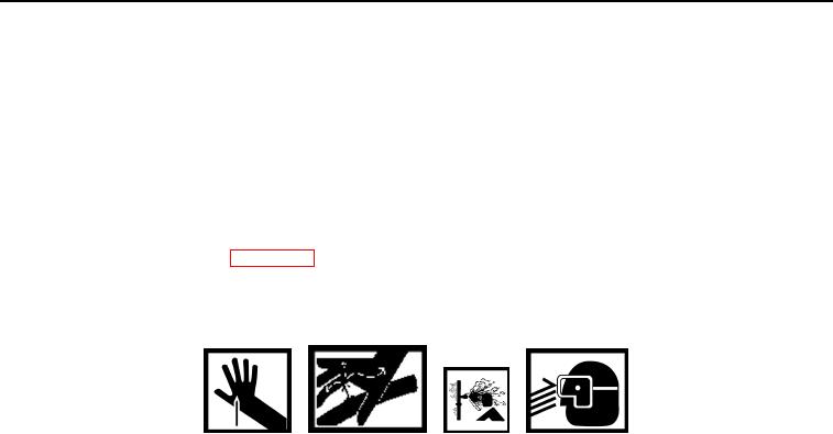
WARNING
Never disconnect hydraulic lines or fittings before venting pressure. Turn dipstick cap 1/4 turn
to safety notch to relieve pressure. Failure to follow this warning may cause death or injury
to personnel.
NOTE
Tag all hose and tube assemblies before disconnecting to aid in installation. Cap and plug
all ports. Remove caps, plugs, and tags following maintenance.
5.
Turn dipstick cap 1/4 turn to safety notch to relieve pressure.
6.
Disconnect and cap hydraulic hoses (Figure 1, Item 8) from elbows (Figure 1, Item 9).
7.
Support cylinder (Figure 1, Item 6). Remove two capscrews (Figure 1, Item 5) and washers (Figure 1, Item 4)
from two pins (Figure 1, Item 3).
8.
Drive out top pin (Figure 1, Item 3).
9.
Remove two washers (Figure 1, Item 2) from each pin (Figure 1, Item 3).
10.
Remove cylinder (Figure 1, Item 6) from carrier (Figure 1, Item 7).
11.
Remove two elbows (Figure 1, Item 9) and two o-rings (Figure 1, Item 1) from cylinder (Figure 1, Item 6).
Discard o-rings.
0152-2
03/15/2011Rel(1.8)root(maintwp)wpno(M00168)

