
SM02-025-0
Page 61
1.
Clean the mounting surfaces and tapped holes
with solvent and the proper tap. Dry thoroughly en-
suring the tapped holes are dry and clean.
2.
Position the drive plate and weld nut assembly
on the impeller cover with the weld nuts toward the
cover.
NOTE
Two dimples 180 degrees apart in the
backing ring must be out (toward the engine
fly wheel).
3.
Align the intermediate drive plate and backing
ring with the holes in the impeller cover.
NOTE
4. Install the special self-locking screws to approx-
imately 0.06 inch (1.5 mm) of the seated position.
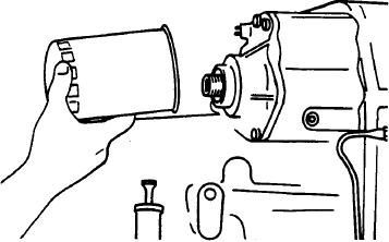
It is recommended that the filter car-
tridge be changed after 50 and 100
NOTE
hours of operation on new and rebuilt or
repaired units.
Assembly of drive plates must be com-
pleted within a fifteen minute period
Install a new oil filter cartridge.
96.
from start of screw installation. The
screws are prepared with an epoxy coat-
Output Shaft Rolling Torque.
ing which begins to harden after installa-
tion. If not tightened to proper torque
1.
Tap the output shaft front and rear to seat the
within a fifteen minute period, insuffi-
taper bearings.
cient screw clamping tension will result.
This special screw is to be used for one
2.
Loosen the front bearing cap bolts.
installation only. If the screw is removed
for any reason it must be replaced. The
3. Using an inch pound torque wrench, determine
epoxy left in the hub holes must be re-
the rolling torque of the output shaft and record this
moved with the proper tap and cleaned
measurement.
with solvent. Dry the hole thoroughly
and use a new screw for reinstallation.
4. Tighten the front bearing cap bolts to the torque
specified in the torque chart and check the rolling
5. With a calibrated torque wrench, torque the
torque again. The rolling torque must be 6 to 8 pounds-
screws 23 to 25 pounds-foot (3.1 to 3.4 kgm).
inch (0.068 to 0.090 kgm) more than when the bear-
ing cap bolts were loose.
5. Add or omit shims on the front bearing cap to
achieve the proper preload.
Drive Plate Installation.
N OTE
To facilitate assembly, align the small
holes in the drive plate.