SM02-027-0
Page 13
2.
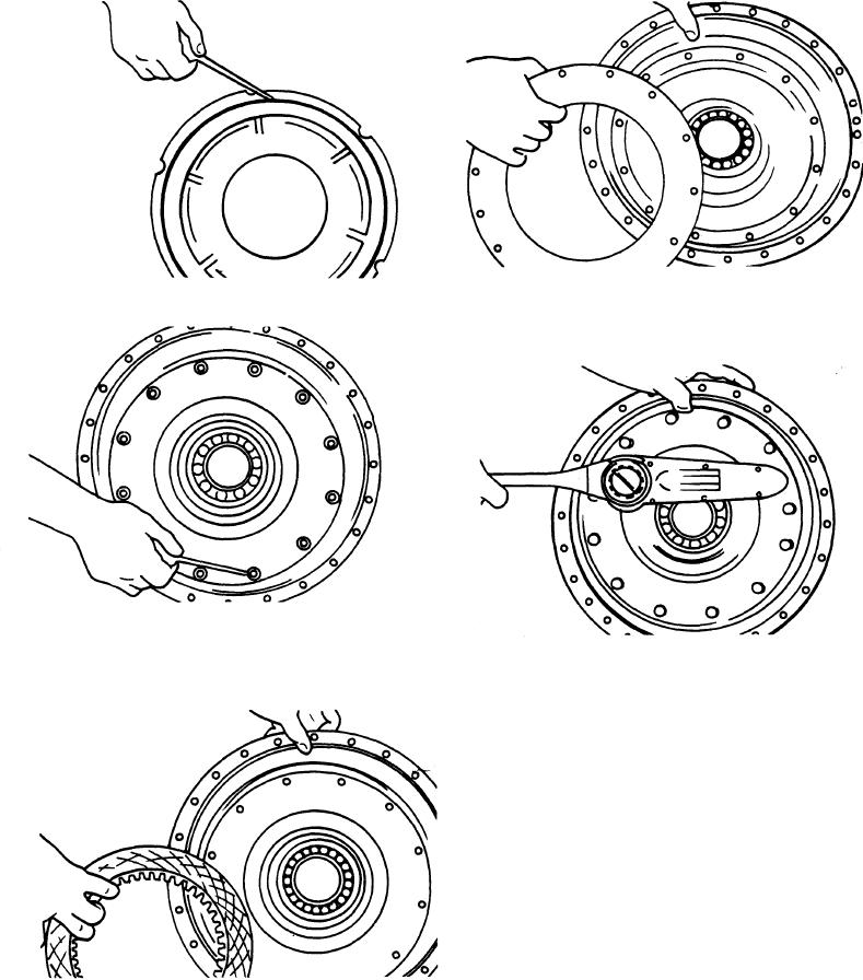
Install the lock-up piston outer O-ring.
5.
Position the disc end plate over the friction disc,
aligning the holes in the end plate with the holes in
the impeller cover.
3.
Position the lock-up piston in the impeller
cover. Locate the spacer sleeves in notches in the
6. Install the self locking capscrews and torque 23
piston and align with the threaded holes in the im-
peller cover.
to 25 pounds-foot (3.1 to 3.3 kgm).
NOTE
If the turbine to turbine hub was replaced
or disassembled, the following proce-
dure must be used for reassembly.
Turbine Hub Assembly with Backing Ring and
Special Self Locking Screws.
1.
Clean the hub mounting surface and tapped
holes with solvent. Dry thoroughly being certain
tapped holes are dry and clean.
4.
Position the lock-up friction disc on the piston.

