TM 5-3810-307-24-1-2
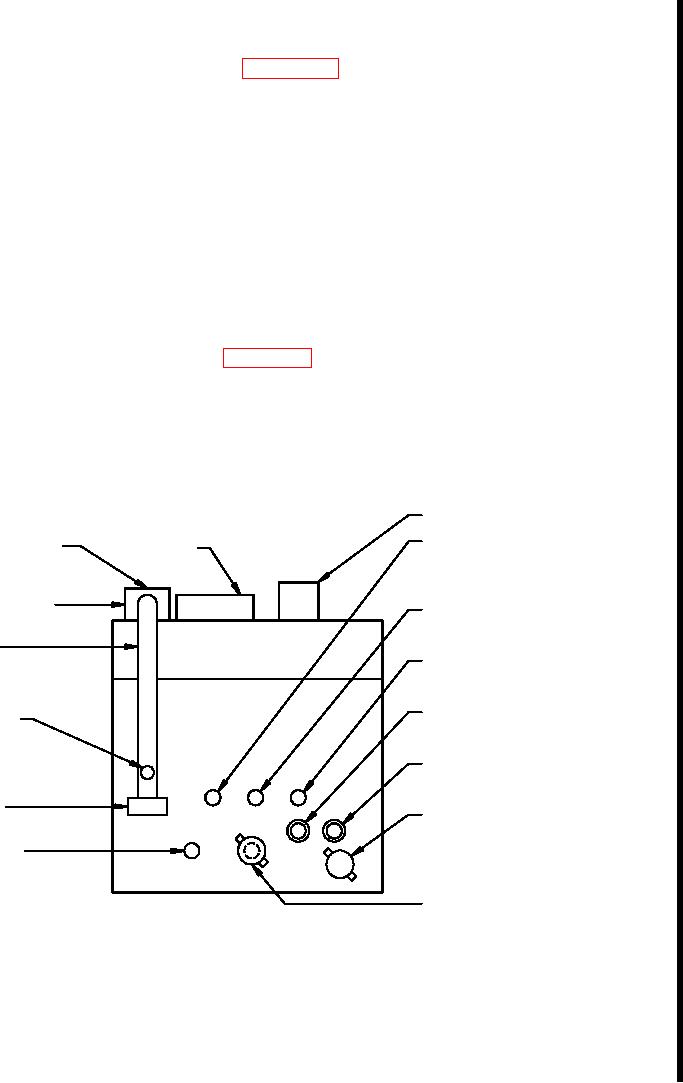
Hydraulic Reservoir Modification. (Refer To Figures J-4, J-5, J-6, and J-7.) Modify the crane's
hydraulic reservoir as follows:
a.
Drain and remove the hydraulic reservoir in accordance with the technical manual, TM 5-
3810-307-24-1-1.
NOTE
Prior to removing hydraulic lines from hydraulic reservoir, loosen all tee
fittings. This will allow easy adjustment to accommodate heater element
coolant connections during reinstallation.
b.
Remove the return filter, sample valve hose connection, breather, and anything that
might be damaged during the modification of the hydraulic reservoir.
c.
Locate the existing engine-driven steer pump suction tank flange on the lower part of the
hydraulic reservoir. Refer to Figure J-4. Install pipe plug - P/N 6443100005 in the
existing tank flange as far as it will go.
NOTE
The engine-driven steer pump suction hose that was connected to the
existing tank flange will be moved to a new 1.25" NPT tank flange - P/N
7450000030 located above the two main hydraulic pump suction fittings.
Breather
Steering Gear Return, Engine-Driven
Return Filter
Filler Cap
& Ground-Driven Steer Pumps By-Pass
Steering Stand-By By-Pass
Oil Sampling
Valve Connection
Swivel Port 7 & Ground-Driven
Steer Pump Drains, Rear Steer Float
Return
Manifold
Engine-Driven Steer Pump Suction
(w/ Espar Engine Coolant Heater)
Integrated
O/R Steer
Main Hydraulic Pump
Valve Return
(Rear Section) Suction
Main Hydraulic Pump
(Forward Section) Suction
Swivel Port
14 Return
Heater Element
(w/ Espar Engine Coolant Heater)
Ground-Driven Steer
Pump Suction
Engine-Driven Steer Pump Suction
(w/o Espar Engine Coolant Heater)
Heater Element
View of Back of Reservoir
(w/ Espar Engine Coolant Heater)
Suction Tubes Rotated
Into Plane of Paper
Figure J-4. Hydraulic Reservoir Connection Legend
Change-1 J-11

