TM 5-3810-307-24-1-2
3
2
HYDRAULIC
1.25" NPT
1
RESERVOIR
TANK FLANGE
LEGEND
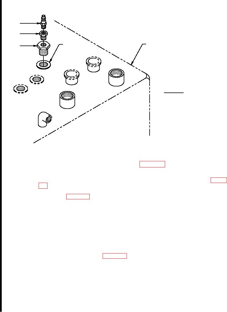
1. 1.25" NPT X 0.5" NPT
adapter fitting
2. 0.5" NPT X 3/8" NPT
adapter fitting
3. 3/8" NPT quick connect
fitting
Figure J-7. Hydraulic Reservoir Test Fitting
Hydraulic Reservoir Heater Element Installation. (Refer To Figure J-8 and J-9.) Install the heating
elements in the modified hydraulic reservoir as follows:
a.
Place Loctite 565 on threads of the two heater elements - P/N H-4000-20 (1, Figure
J-8) and install in 2.0" NPT couplers - P/N A-3228HD installed on hydraulic reservoir.
Tighten until COOLANT IN or OUT points toward the lower RH corner of tank. Refer to
the detail on Figure J-8.
b.
Place Loctite 565 on threads of four 0.5" X 0.75" pipe bushings - P/N A-282 (2), install
in COOLANT IN and OUT of each heater element (1), and tighten.
c.
Place Loctite 565 on threads of four 0.75" brass elbows - P/N A-653 (3), install in each
0.5" X 0.75" pipe bushing P/N A-282 (2), and tighten.
d.
Carefully place the hydraulic reservoir on its mounting bracket and check for interference
between the heater elements/fittings and the mounting bracket. If necessary, mark the
point of interference, remove the tank, and cut a half-moon notch in the front hydraulic
reservoir bracket as shown in Figure J-9. Repaint the modified mounting bracket.
e.
Reinstall hydraulic reservoir in accordance with the Technical Manual, TM 5-3810-307-
24-1-1.
NOTE
Due to the fact that the engine-driven steer pump suction location has
been moved, the existing set of fittings may have to be completely
disassembled and reassembled at the new location.
J-16 Change-1

