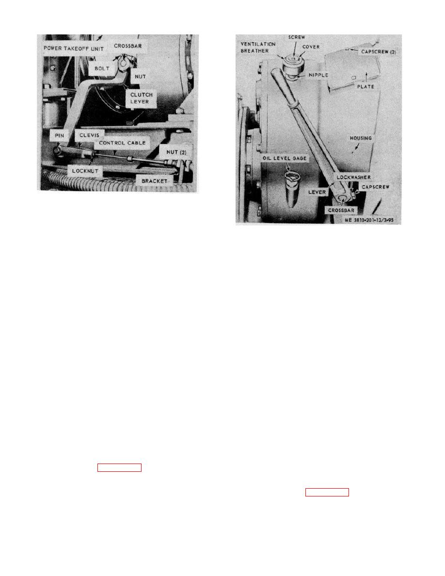
STEP 1. REMOVE PIN FROM CLEVIS AND CLUTCH
LEVER.
STEP 2. REMOVE NUT AND BOLT FROM, ' CLUTCH
LEVER AND REMOVE. CLUTCH LEVER
Figure 3-95. Auxiliary clutch lever and ventilation
FROM CROSSBAR.
breather, removal points.
STEP 3. LOOSEN LOCKNUT AND CLEVIS FROM
CONTROL
STEP 4. LOOSEN TWO NUT AND REMOVE
CONTROL CABLE FROM BRACKET.
STEP 5. REMOVE
CONTROL
CABLE
FROM
OPERATOR'S
CONTROL
LEVER
BY
REPEATING STEPS 1 AND 3, REMOVE ALL
CLAMPS HOLDING CABLE TO CAB
FRAME, THEN REMOVE CONTROL CABLE.
ME 3810-201-12/3-94
Figure 3-94. Clutch lever and linkage, removal and
installation.
Section XVI. POWER TRANSFER
(3) Install in reverse order.
3-110. General
b. Cleaning, Inspection and Repair.
The main drive chain case is located at right rear side of
(1) Clean all parts in an approved cleaning
crane-shovel unit inside the cab. The case completely
solvent and dry thoroughly.
Use low pressure
surrounds the input and main shaft sprockets, and the
compressed air to dry breather (filter).
transfer chain. The transfer chain is a multiple strand
(2) Visually inspect screw for burs or stripped
roller chain which connects input and main shaft
threads. Inspect breather for excess clogging of filter
sprockets.
portion.
(3) Repair by replacing a defective breather or
3-111. Ventilation Breather (Filter)
screw.
a. Removal and Installation.
(1) Refer to figure 3-95, remove screw, and
3-112. Transfer Chain Case Cover
cover, from ventilation breather (filter).
a. Removal and Installation.
(2) Remove ventilation breather (filter) from
(1) Refer to figure 3-96 and remove transfer
nipple by turning counterclockwise.
Remove a
chain case cover.
damaged nipple.
3-106


