TM 5-3810-206-35
(3) Inspect shaft and bearings for scoring,
(2) Install in reverse order. Torque retainer nuts
damage, or wear. Replace scored or damaged shaft
to between 100 and 110 ft-lbs.
and bearings.
The bore of new bearings should
b. Disassembly and Reassembly.
measure between 0.4950 and 0.4956 inch, and the
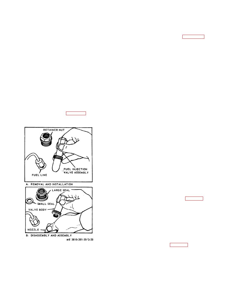
(1) Refer to view B of figure 3-25 and
diameter of a new shaft should measure between 0.4936
disassemble the fuel injection valve(s).
and 0.4938 inch.
The specified shaft to bearing
(2) Reassemble in reverse order.
clearance is between 0.0012 and 0.0019 inch. Replace
c. Cleaning, Inspection, and Repair.
bearing and/or shaft when clearance exceeds 0.003
(1) Clean all parts using any process required to
inch.
thoroughly clean, but not damage the part. Remove all
(4) Inspect gear cover for scoring or other
carbon deposits. Remove carbon from nozzle with a drill
damage. Measure for clearance. The specified gear to
corresponding to the orifice size stamped on side of fuel
cover clearance is between 0.0010 and 0.0022 inches.
injector valve.
Replace gear(s) and/or cover when clearance exceeds
(2) Inspect the valves for visible damage, and
0.0035 inches.
test for proper operation by mounting valve on test
(5) Inspect pump body, cover, or seat for cracks
fixture, examining the spray pattern, and checking the
or breaks. Repair by welding, or replace a defective
valve unseating pressure.
Replace a damaged or
part.
defective valve. Unseating pressure must be between
400 and 800 psi. If applied pressure fails to reach 400
psi, discard the valve. Test for leakage by applying 300
3-19. Fuel Injection Valves for Engine Model D333TA
psi pressure. If pressure falls more than 100 psi in 30
a. Removal and Installation.
seconds, replace the valve. Replace a valve that does
(1) Refer to view A of figure 3-25 and remove
not produce an even atomized spray pattern after the
the fuel injection valve(s).
orifice has been cleaned. If screen filter in the valve is
broken or clogged, replace the valve.
Note. Only the capsule type nozzle
and valve body need be replaced.
Tighten nozzle on valve body only
finger tight.
3-20. Fuel Injection Pump for Engine Model D333TA
a. General. This fuel injection pump is composed
of six individual fuel pumps in one housing; cam shaft
operated to assure timing, and driven by an adapter from
the accessory drive shaft.
b. Removal and Installation.
(1) Remove all fuel lines from governor, fuel
injection pumps and housing, fuel filter, fuel transfer
pump, and governor control linkage (TM 5-3810-206-12).
(2) Remove fuel filter (TM 5-3810-206-12).
(3) Remove fuel transfer pump (para 3-18).
(4) Remove six capscrews and lockwashers
securing the fuel pump housing to accessory drive
housing adapter.
(5) Remove fuel injection pump housing and
governor from engine as a unit by moving it to left until
drive gear is free of the adapter, then moving to an area
for disassembly.
(6) Install fuel pump housing by reversing the
procedures in steps (1) through (5) above.
c. Disassembly and Reassembly.
(1) Remove governor (para 3-10).
Figure 3-25. Fuel injection valve, removal, disassembly,
reassembly, and installation.
3-33


