TM 5-3810-206-35
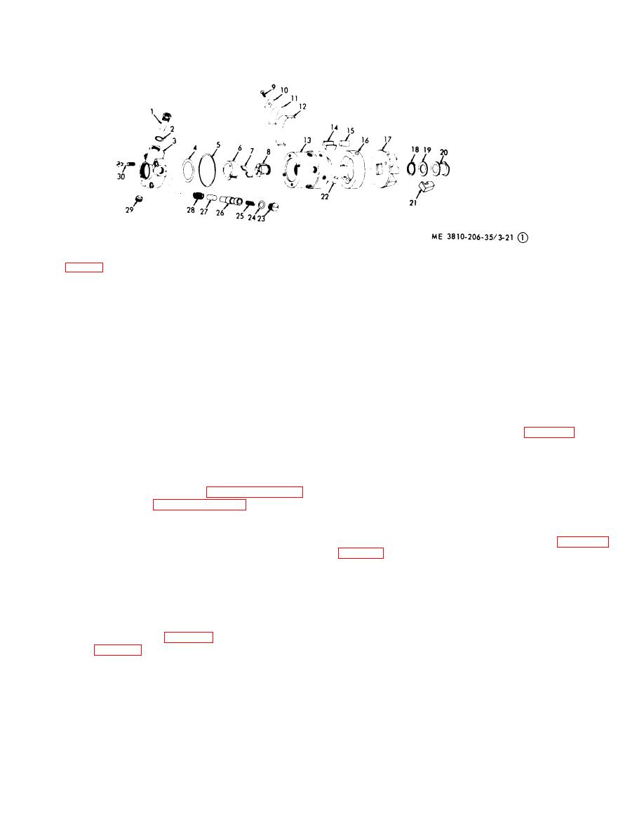
(Figure 3-21 Sheet 1 of 2)
(Figure 3-21 Sheet 2 of 2)
KEY to fig. 3-21:
1
Cap and filter
9
Screw
15
Cam roller
23
Plug (3 rqr)
element
10
Spring plate,
(2 rqr)
24
Packing (2 rqr)
2
Packing
third
16
Cam ring
25
Spring
3
End plate
11
Spring plate,
17
Weight retainer
26
Sleeve
4
Packing
second
18
Retaining ring
27
Piston
5
Packing
12
Spring plate,
19
Thrust washer
28
Spring
6
Liner
main
20
Bearing, sleeve
29
Pipe plug
7
Blade
13
Head and rotor
21
Weight (6 rqr)
30
Screw (4 rqr)
8
Rotor retainer
14
Shoe (2 rqr)
22
Metering valve
(2 rqr)
Figure 3-21. Fuel injection pump, exploded view (sheet 1 of 2).
(12) Lift arm (47) and link (46) out of housing
(25) Place special tool (4, fig. 3-23) over
(51).
distributor rotor (3), and special tool (5) in tongue slot of
(13) Remove bolt (38), fuel line connector screw
distributor rotor (3), loosen then remove distributor rotor
(73) packing (74), cam hole seal (62) screw (63),
(3) from head.
packing (64) and washer (75) from housing (51).
(14) Lift head and rotor (13, sheet 1 of fig. 3-21)
Note.
At reassembly, insure that
out of pump housing (51, sheet 2 of fig. 3-21).
etched arrow indicating distributor
(15) Insert a finger in bore of sleeve bearing (20)
rotor rotation is correctly installed.
and lift upward until it disengages with weights (21).
(16) Remove sleeve bearing (20), thrustwasher
(26) Remove weight retaining ring (18, sheet 1 of
(19), and weights (21).
(17) Remove four screws (30) and lift end plate
head (13).
(3) off head and rotor (13).
(27) Apply compressed air (between 30 to 100
(18) Remove pipe plug (29) from end plate (3).
psi) to all head outlets until cam rollers (15) are forced to
(19) Remove packing (4) from end plate (3).
their extreme outward limit. Carefully measure the
(20) Remove plug (23), packing (24), and spring
distance from outside of 1 cam roller to the other by a
(25) from sleeve (26).
micrometer with a one to two inch jaw. This distance
(21) Insert tool (2, fig. 3-22) in hole in top of
must be maintained at reassembly.
sleeve (26, fig. 3-21) and remove sleeve (26), piston
(28) Remove screw (9) and spring plates (10, 11,
(27), spring (28), and packing (24) from end plate (3).
and 12), from head and rotor.
(22) Remove cap and filter element (1) and
packing (2) from end plate (3).
Note.
Use extreme care when
(23) Remove packing (5) from head and rotor
removing metering valve from head
(13).
and rotor, so as not to mar the
(24) Lift liner (6) and blades (7) o t of head and
u
machined surfaces.
rotor (13).
3-29


