TM 5-3810-206-35
(2) Remove all external fuel and oil lines from
(3) Pry shutoff cam (2) away from housing (14)
fuel pump and drive mechanism (TM 5-3810-206-12).
and slide cam (10) out of its groove and off throttle shaft
(3) Disconnect governor control linkage (TM 5-
and lever (37, sheet 2 of fig. 3-21).
3810-206-12).
(4) Remove shutoff shaft (55) and packing (58).
(4) Remove timing hole cover from fuel pump
(5) Remove throttle shaft (37) from housing
housing (14, fig. 3-19), then turn crankshaft clockwise
(51), remove three screws (33), lockwashers (34), and
until governor weight timing mark (8) is aligned with cam
separate throttle arm (31) from throttle shaft (37).
timing mark (7).
(6) Remove adjusting screws (365 and 56) and
(5) Remove three nuts (25, fig. 3-18) and
nuts (36 and 57) as required.
washers (24) then lift fuel injection pump (10) off drive
(7) Compress spring (45), retainer (44), idler
mechanism (21).
spring (43), and guide (42), then remove from guide stud
(6) Remove three nuts (3) and lockwashers (2)
(81).
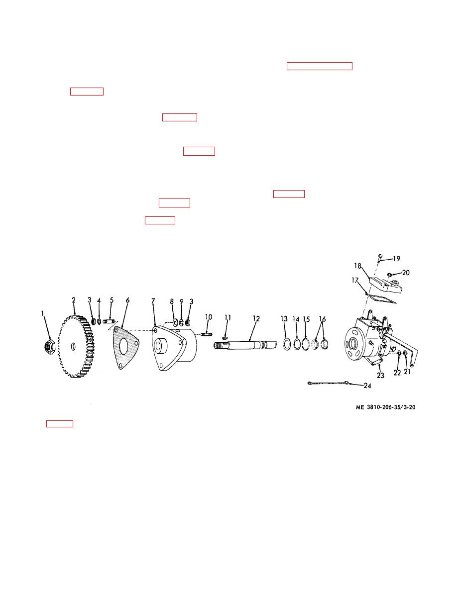
then lift drive mechanism (21) and gasket (6, fig. 3-20)
(8) Remove guide stud (81) and washer (82)
from engine.
from housing (51).
(7) Install fuel injection pump and drive
(9) Raise link (46) at metering valve (50), pull it
mechanism by reversing the procedures in steps (1)
back slightly then disengage link (46) from arm (47).
through (6) above.
(10) Place link (46) aside, then remove metering
b. Disassembly and Reassembly.
valve (5, fig. 3-19) from housing (14). Use care not to
(1) Remove three screws (19, fig. 3-20), cover
crack valve while lifting it from housing.
(18) and gasket (17) from pump housing (23).
(11) Remove nut (54), packing (53), and shaft
(2) Rotate shutoff shaft (1, fig. 3-19) to full shut-
(52) from housing (51).
off position.
KEY to fig. 3-20:
1
Nut
7
Adapter
13
Thrustwasher
19
Screw (3 rqr)
2
Gear
8
Washer (3 rqr)
14
Retaining ring
20
Nut
3
Nut (3 rqr)
9
Washer (6 rqr)
15
Seal
21
Nut (3 rqr)
4
Lockwasher, IET
10
Stud (3 rqr)
16
Seal (2 rqr)
22
Flatwasher (7 rqr)
(3 rqr)
11
Key
17
Gasket
23
Housing
5
Stud (3 rqr)
12
Shaft
18
Cover
24
Ground strap
6
Gasket
Figure 3-20. Pump drive mechanism, exploded view.
3-28


