TM 5-3810-206-35
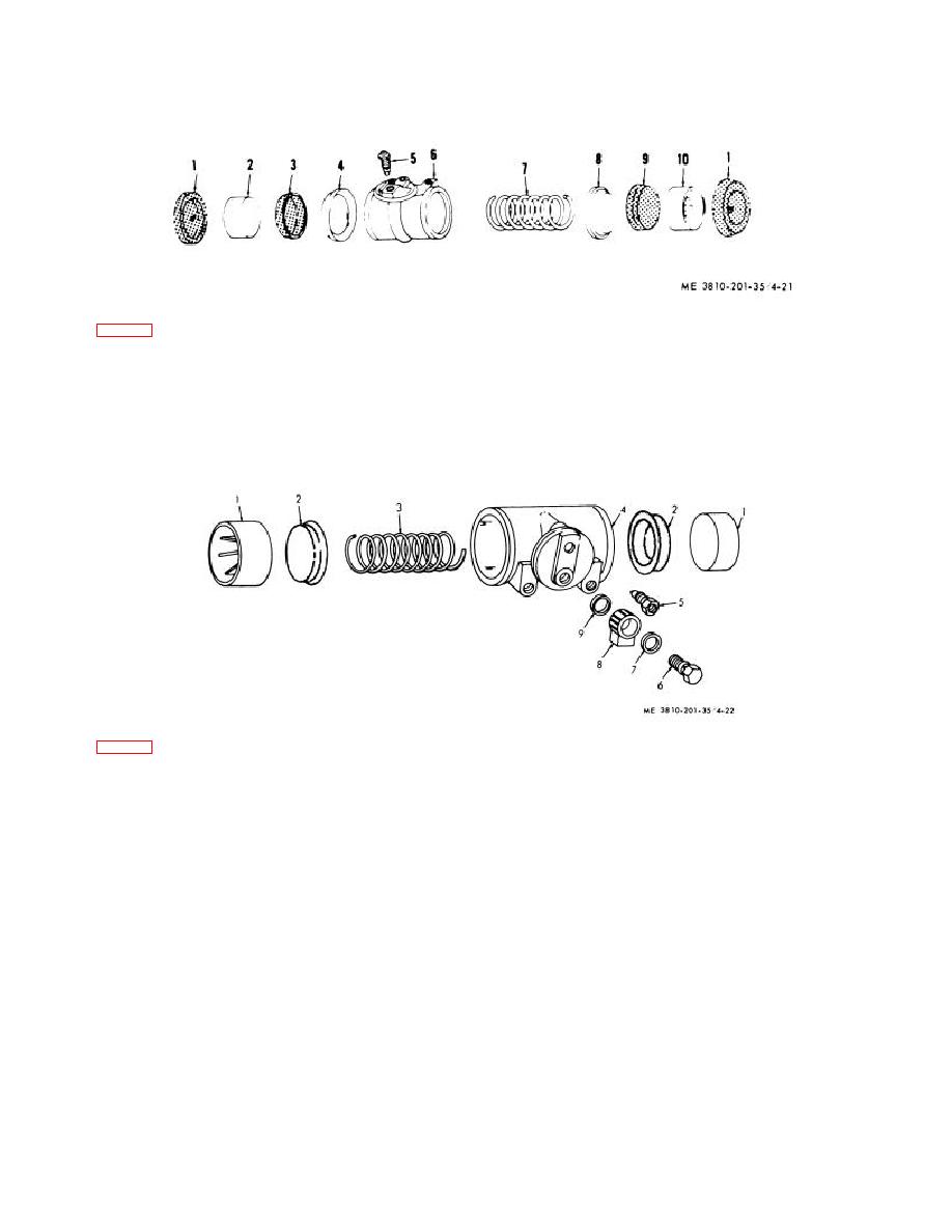
KEY to fig. 4-21:
1
Boot (2 rqr)
4
Expand er
7
Spring
9
Cup
2
Piston
5
Bleeder valve
8
Expander
10
Piston
3
Cup
6
Cylinder body
Figure 4-21. Hydraulic brake cylinder, exploded view.
KEY to fig. 4-22:
1
Piston (2 rqr)
4
Cylinder
6
Fluid passage bolt
8
Fitting
2
Cup (2 rqr)
5
Bleeder valve
7
Washer
9
Gasket
3
Spring
Figure 4-22. Planetary, hoist, digging, and boom brake hydraulic cylinder.
(2) Remove piston (2), cup (3) and expander (4)
breaks, scored surfaces, or ridges of gummed fluid.
from cylinder (6).
Inspect return spring for deformation and test for tension
(3) Remove spring (7) from cylinder (6). Then
strength. Inspect bleeder valve for damage or defect.
remove piston (10), cup (9), and expander (8), from
(3) Repair by honing away gummed ridges or
cylinder (6).
light scoring of pistons or cylinder. Replace defective
(4) Remove the bleeder valve (5).
components.
(5) Reassemble by reversing steps (1) through
(4) above.
4-37. Planetary, Hoist, Digging, and Boom Brake
c. Cleaning, Inspection, and Repair.
Wheel Cylinders
(1) Clean all parts and dry thoroughly.
(2) Inspect boots and cups for deformation or
a. Removal and Installation. Remove or install
signs of deterioration. Inspect cylinder and pistons for
hydraulic brake cylinders (TM 5-3810-206-12).
4-31


