TM 5-3810-206-35
Section XV. REVOLVING FRAME AND HOOK ROLLERS
and prevent frame from tipping. The engine mounting
4-31. General
base is welded to platform at rear of revolving frame.
The revolving frame is a deep box section of metal
construction, with rolled steel sidestands welded in place
4-32. Front Hook Rollers
for machinery mounting. The platform is welded to
revolving frame, and covers for the deep box section
a. Removal and Installation of Front Hook Rollers.
holds slug punching portion of counterweight in place.
Remove or install front hook rollers (TM 5-3810-206-12).
The counterweight extension mounts on rear of revolving
b. Removal or Installation of Front Hook Roller
frame, and the front end attachments mount their boom
Bracket.
at front. The hook rollers, bolted underneath revolving
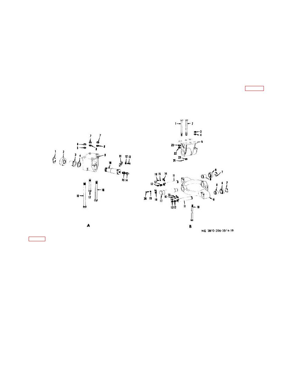
(1) Remove two nuts (6, view A of fig. 4-19),
frame, hook over roller circle of crawler carbody,
lockwashers (5), and bolts (18) from bracket (9).
KEY to fig. 4-10:
A Front hook roller
B Rear hook roller
1
Retainer (2 rqr)
10
Shaft (2 rqr)
1
Bolt (4 rqr)
12
Pipe bushing
2
Roller (2 rqr)
11
Keeper plate
2
Bolt (4 rqr)
(4 rqr)
3
Bearing (2 rqr)
(2 rqr)
3
Nut (4 rqr)
13
Fittings (4 rqr)
4
Flatwasher
12
Lockwasher
4
Lockwasher
14
Lockplate (4 rqr)
(2 rqr)
(4 rqr)
(4 rqr)
15
Lockw asher (8 rqr)
5
Lockwasher
13
Capscrew (4 rqr)
5
Bracket (2 rqr)
16
Capscrew (8 rqr)
(4 rqr)
14
Fitting (2 rqr)
6
Roller (4 rqr)
17
Pin, eccentric
6
Nuts (4 rqr)
15
Pipe bushing
7
Retainer
(2 rqr)
7
Nut (4 rqr)
(2 rqr)
(4 rqr)
18
Keeper plate (2 rqr)
8
Lockwasher
16
Screw (2 rqr)
8
Bearing (4 rqr)
19
Lockwasher (4 rqr)
(6 rqr)
17
Bolt (4 rqr)
9
Swivel arm
20
Capscrew (4 rqr)
9
Bracket (2 rqr)
18
Bolt (4 rqr)
(2 rqr)
21
Cotterpin (4 rqr)
10
Bolt (4 rqr)
22
Nut (8 rqr)
11
Pin (4 rqr)
23
Lockwasher (8 rqr)
Figure 4-19. Front and rear hook rollers, exploded view
4-28


