TM 5-3810-207-20/TO 36C23-3-37-12
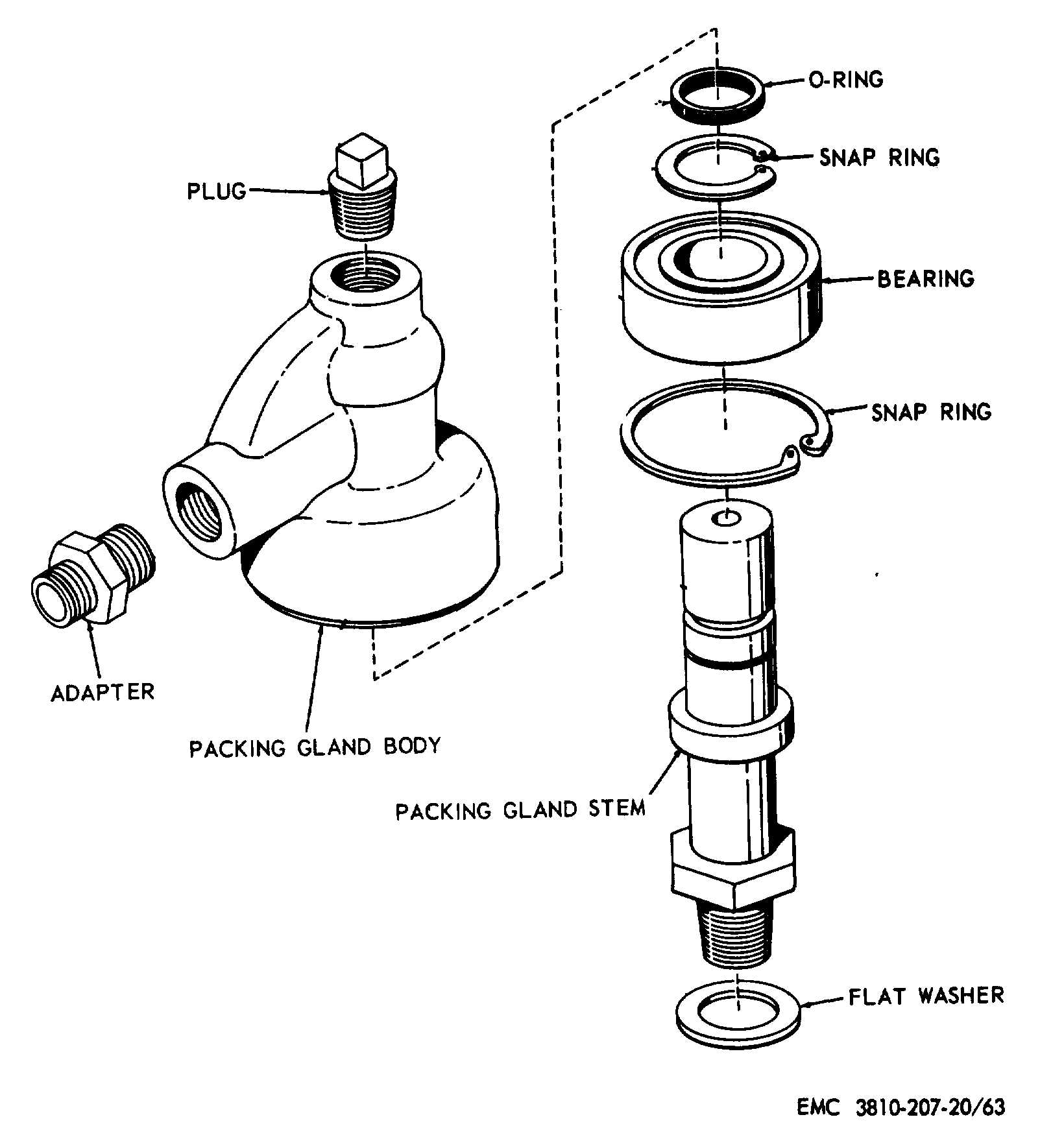
Figure 63. Packing gland, exploded view.
(3)
Remove the swing clutch control lever as
instructed on figure 65.
(4)
Remove the power-down boom lever,
primary drum clutch lever, and secondary
drum clutch lever in the same manner.
b.
Cleaning, Inspection, and Repair.
(1)
Clean all parts with an approved cleaning
solvent.
(2)
Inspect all parts for excessive wear, breaks,
cracks, and other damage. Repair by
welding or replace all defective parts.
c.
Installation.
(1)
Install the swing clutch control lever as
illustrated on figure 65.
(2)
Install the master cylinder linkage to the
swing clutch control lever (par. 129).
(3)
Install the dust shield to the revolving
frame.
(4)
Install the power-down boom lever, primary
drum clutch lever, and secondary drum
clutch lever in the same manner.
95