TM 5-3810-207-20/TO 36C23-3-37-12
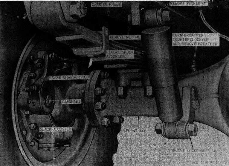
Figure 178. Right-front shock absorber and differential breather, removal and installation.
Section III. CARRIER AIRBRAKE SYSTEM
290. General
The carrier is equipped with service brakes on all six
wheels, controlled by the airbrake system. In this
airbrake system, the brakes are set by the power of
compressed air and set faster and more effectively than
manual footbrakes. The air system consists of an air
compressor, valves, reservoirs, brake chambers, and
connecting hoses, tubes, and fittings. The air
compressor furnishes the compressed air needed to
operate the brakes. The compressor is a two-cylinder,
engine-lubricated,
watercooled,
single-acting,
reciprocating type located on the right-front side of the
engine, and driven by a V-belt from the engine
crankshaft.
291. Air Lines, Hoses, and Fittings
a.
Removal.
(1) Remove
the
screws
and
clamps
securing airhoses and lines to carrier
frame.
(2) Disconnect the air hoses and lines from
the valves, brake chambers, and air
compressor; remove lines and hoses.
Refer to the carrier airbrake system
piping diagram (fig. 179).
b.
Cleaning and Inspection.
(1) Clean all lines and hoses with an
approved cleaning solvent.
(2) Inspect the lines for dents, breaks, and
wear.
231


