TM 5-3810-231-12
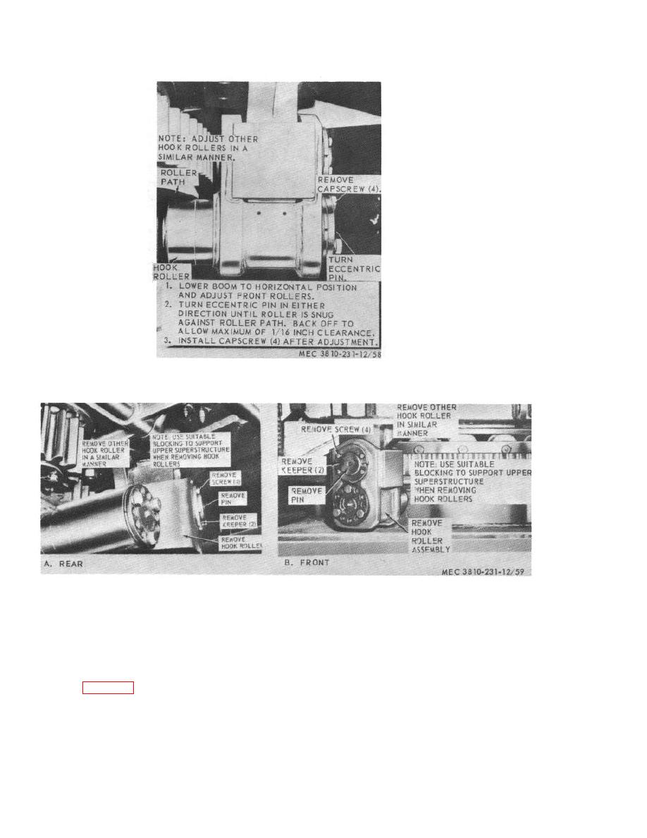
Figure 58. Hook roller adjustment.
Figure 59. Hook roller assembly, removal and installation.
Section XVII. CRANE BRAKE AND CLUTCH ASSEMBLIES
mechanisms are used to actuate the various brakes and
111.
General
These assemblies differ in size of the
hydraulic cylinder used and number or size of the
The location of the various brakes and clutches are
release springs used. Adjustments for all of the unit are
shown in figure 60. Brakes and clutches should be kept
the same.
in proper adjustment as a safety measure, and for
proper operation.
Hydraulic cylinder operating
89


